 FEXLINK Research Institute
The short answer
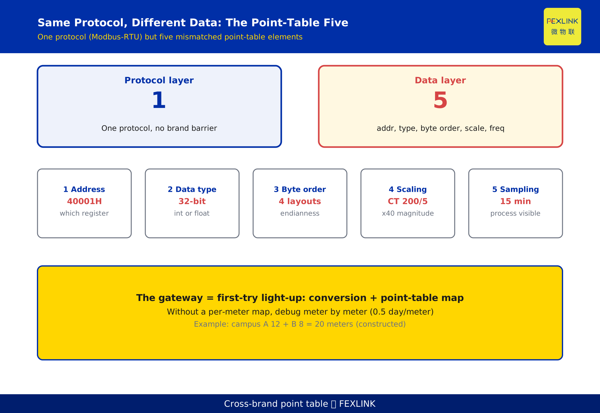
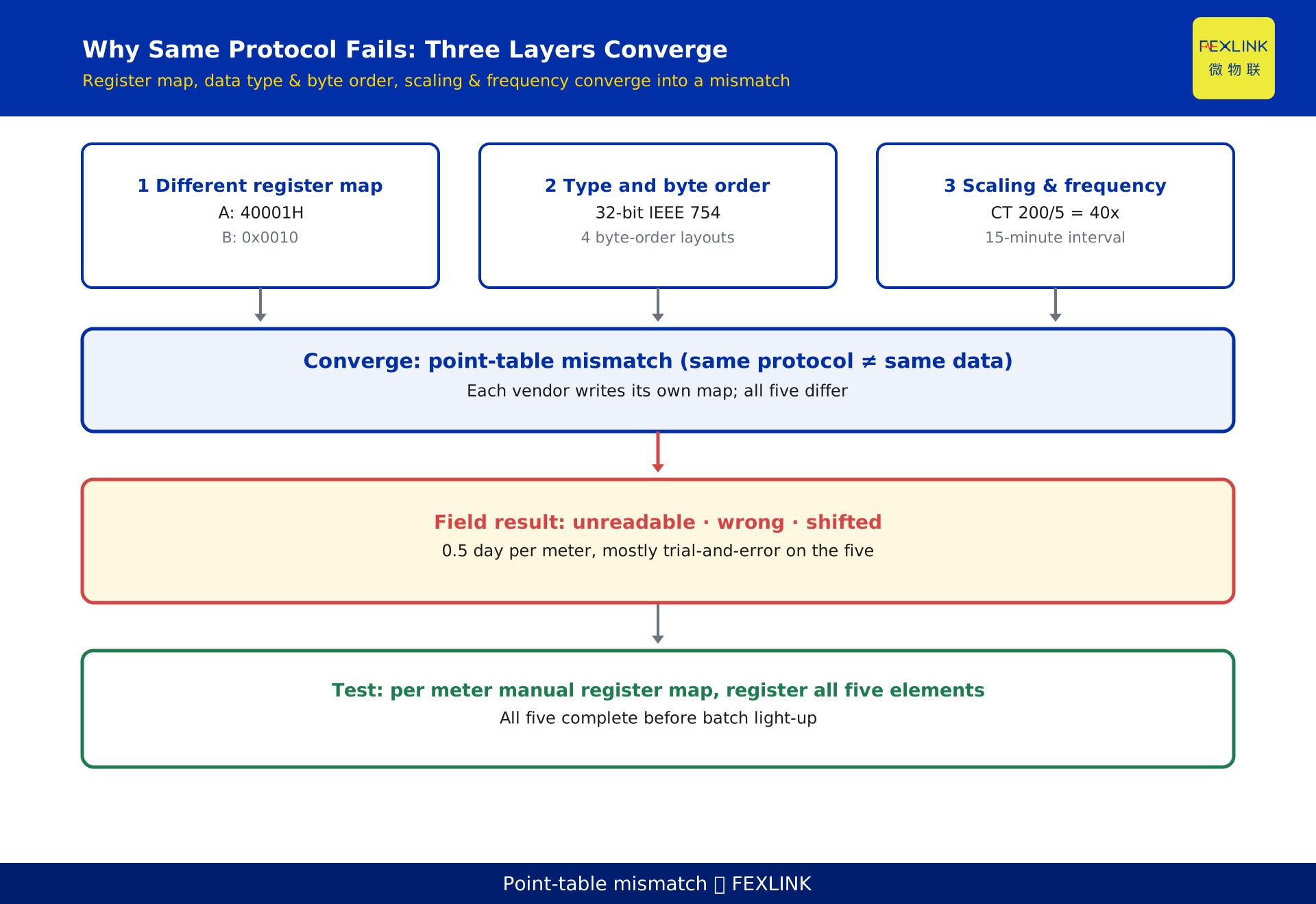
When a campus has both Brand A and Brand B meters and the platform cannot line up their fields after onboarding, the root cause is not the protocol. Both use Modbus-RTU, so the protocol layer is identical; the bottleneck is the "point table." Register address, data type, byte order, scaling factor and sampling frequency must be mapped meter by meter. Get any one wrong and the value is unreadable or wrong. The gateway performs protocol conversion and point-table configuration, and that is what decides whether a project lights up on the first try. The test is simple: is there a per-meter point-table map before wiring, and if so the site lights up once; if not, meters are debugged one at a time.
1. Why "they are all Modbus meters" still fails to read
Installers often say "they are all Modbus meters, why can't we just read them directly." That is half right. Modbus is a published serial communication protocol (Modbus-IDA / Schneider public specification); data exchange goes through register reads and writes, and the protocol itself has no brand barrier. Energy, power and voltage, regardless of brand, all end up in holding registers (the 4xxxx range) and are read with function code 0x03.
But "communication works" and "the number read is correct" are two different things. Modbus only defines how to read a register; it does not define which register holds what, or in what format. The register map is the private part each vendor defines. Brand A may place active power in holding register 40001H, Brand B at 0x0010; for the same register, Brand A may use a 32-bit IEEE 754 float while Brand B packs two 16-bit integers. The protocol is fine, yet the numbers are shifted, scaled, or simply zero — that is the point-table mismatch.
2. The five elements of point-table mapping
What truly must be checked meter by meter is the following five-piece set, none dispensable:
- Register address: which holding register the value sits in, and the offset.
- Data type: 16-bit integer, 32-bit integer, 32-bit IEEE 754 float, or BCD.
- Byte order: for 32-bit values, big-endian or little-endian, and word order (high/low word first) — this alone decides whether the reading is a valid number or garbage.
- Scaling factor: primary-side energy = secondary-side reading × ratio (for example a CT ratio of 200/5, i.e. 40×); a wrong scaling factor is an order-of-magnitude error.
- Sampling frequency: how often a point is polled; energy monitoring commonly uses a 15-minute interval, and too coarse an interval flattens the demand peak.
Of these five, address, type and byte order decide whether the value can be read correctly; scaling decides whether the number is right; frequency decides whether the process is visible. Debugging one meter for half a day (0.5 day per meter) is mostly spent trial-and-error on these five.
3. Register address: the first gate
The register address is the first column of the point table. Modbus holding registers start at 40001, but vendors notate them differently: some write 40001H, some 0x0000, some only give an offset. The same "active power" sits at 40001H for Brand A and at 0x0010 for Brand B, so they must be configured separately.
More subtle is whether registers are contiguous. Some meters split a 32-bit value into two adjacent 16-bit registers; some insert reserved bits in between. Copying another vendor's address table reads either shifted or out of range. There is no shortcut: use each meter's manual register map, register meter by meter, and never "guess because it looks similar."
4. Data type and byte order: how to read a 32-bit energy value
Values with decimals, like energy and power, are almost always 32-bit. The problem is byte order. A 32-bit IEEE 754 float has four possible layouts: big-endian byte order, little-endian byte order, big-endian word / little-endian byte order, and little-endian word / big-endian byte order. If Brand A stores big-endian and the platform decodes little-endian, what comes out is not a number but an entirely unrelated float.
This is the most typical "garbage but not zero" case in cross-brand onboarding: communication is fine, the register address is right, only the byte order is wrong, and the whole value drifts. The only rule: follow the byte order marked in the vendor's register map and set it explicitly in the gateway; never guess.
5. Scaling and sampling frequency: restoring the true energy
Scaling fixes the magnitude. When a meter is connected through a current transformer (CT), it reads the energy on the secondary side, and the primary-side true energy must be restored by multiplying the ratio. A CT ratio of 200/5 (i.e. 40×) is a common example; getting the ratio wrong by one step throws the whole circuit's energy off by 40×. Scaling is a mandatory point-table field and must be checked item by item against the field CT nameplate.
Sampling frequency fixes visibility. Energy monitoring commonly samples at a 15-minute interval, aligned with the demand period; too coarse an interval flattens peaks and demand, and later demand optimization loses its basis. Frequency is set by monitoring purpose, not by "faster is better," but it must be pinned in the point table.
6. Where the gateway sits in cross-brand onboarding
Protocol conversion and point-table configuration live at the gateway layer. The platform side should not, and need not, adapt to every brand's private register map — that would be endless. The right approach: the gateway connects southward to multi-brand meters (uniform Modbus-RTU polling) and northward to the platform (reporting against the platform data model), doing two things in between —
First, protocol convergence: normalizing different physical interfaces and polling rhythms. Second, point-table translation: translating each meter's private register map into the platform's unified data points. Both the FEXLINK ESX series edge computing gateway (edge-side protocol conversion and data aggregation) and the FEXLINK CW industrial gateway (field-side protocol access) play this role; they differ in deployment position and compute — ESX leans edge aggregation, CW leans field access.
A misconfigured gateway shows the platform a pile of wrong values or empty points; a correctly configured one shows only a clean, unified data model — that is the line between "lights up once" and "debugged meter by meter."
7. Onboarding sequence for mixed legacy fleets
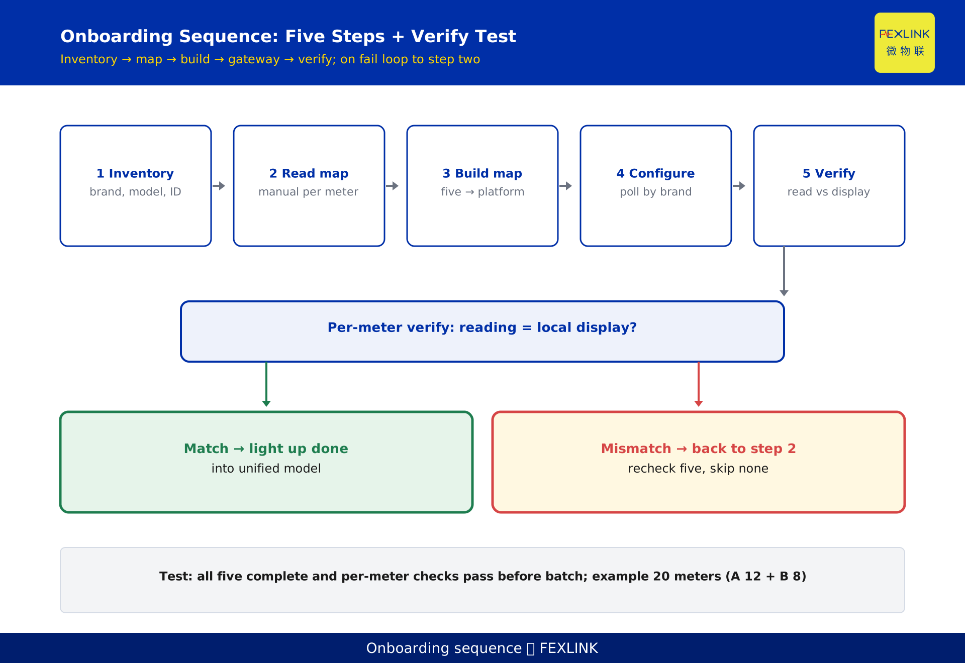
Existing campuses are often a mix of Brand A and Brand B. In an illustrative scenario a campus has 12 Brand A meters and 8 Brand B meters, 20 in total (constructed to explain the problem, not a real customer). Onboarding must follow a fixed sequence; do not attempt full light-up on day one:
Step 1, inventory the meters: list each meter's brand, model, communication port and slave address. Step 2, read the register maps: find the manual for each meter and register the five elements. Step 3, build the point-table map: unify to platform point names, writing address, type, byte order, scaling and frequency per meter. Step 4, configure and push to the gateway: load the map into the gateway and poll grouped by brand. Step 5, light up and verify per meter: compare each meter's reading against its local display; only a match passes.
The step most often skipped is Step 2 — copying a neighbor's address to save effort, after which meter three onward is all wrong.
8. What a standard point-table template looks like
A reusable point-table template is, per row, the five-element checklist for one meter plus the platform-side target point name. Typical columns:
meter ID / brand and model / slave address / data point (e.g. "total active power") / register address / data type / byte order / scaling factor / sampling frequency / platform point name.
The value of the template is not its format but its compulsion to register meter by meter and to keep all five elements complete. Any cell marked "unknown" or "same as neighbor" is a point that will blow up at light-up. Archive the template together with the gateway configuration as the foundation for later operation and handover.
9. FAQ
Q: They are all Modbus meters, so why can't we just copy the point table?
You cannot. Modbus only defines the communication method; the register map is the vendor's private definition, and addresses, types, byte orders and scaling differ. Copying a neighbor assumes two vendors share a register map, which almost never holds in practice.
Q: The comms light is on and we can read values — is it done?
Not necessarily. Reading a value only means the protocol works; whether the number is right depends on byte order and scaling. The common case is normal comms but wrong byte order, yielding drifting garbage rather than zero, which is most easily mistaken for "already connected."
Q: Can the gateway automatically identify each brand's point table?
Not fully automatic today. Gateways can auto-discover slaves and auto-poll, but the register map still must be entered or imported manually per the manual. So-called "auto-adapt" mostly means batch copy for the same brand and model; cross-brand still needs per-meter mapping.
Q: What happens if the scaling factor is wrong?
An order-of-magnitude error. A CT ratio of 40× set to 1 throws the whole circuit's energy off by 40×; set backwards it may even go negative. The scaling factor must be checked item by item against the field CT nameplate, never left at a default.
Q: What sampling frequency should I set?
Set it by monitoring purpose. Energy monitoring commonly uses 15 minutes, aligned with the demand period; demand optimization wants finer (e.g. 1 minute), while general energy statistics at 15 minutes is enough. Pin the frequency in the point table and adjust uniformly later.
Scope and limitations
- The cross-brand meter onboarding problem discussed here specifically concerns mixed multi-brand fleets all using Modbus-RTU. Involving other protocols such as DL/T 645, MQTT or BACnet belongs to protocol conversion and differs from this article's "same protocol, different point table" angle (see KD-0485).
- The illustrative scenario's "a campus with 12 Brand A meters and 8 Brand B meters, 20 in total," "debugging half a day per meter (0.5 day/meter)," "Brand A 40001H, Brand B 0x0010," and "CT ratio 200/5 (40×)" are all constructed to explain the problem and represent no real customer, project or device specification.
- Example values for register address, data type and byte order demonstrate the five-element difference mechanism and are not any real device's register map; actual onboarding must follow each meter vendor's manual register map.
- The "15-minute" sampling frequency is an example of a common energy-monitoring interval; the actual value is set by monitoring purpose and platform requirements and is not a mandatory standard.
- Model numbers and specifications for the FEXLINK ESX series edge computing gateway, CW industrial gateway and digital electrical intelligent supervision system follow the latest selection manual and product knowledge base; this article is not a selection or procurement recommendation.
- Standards cited — the Modbus protocol specification (Modbus-IDA / Schneider public documents) and the GB/T 17215 series of electricity metering standards — are current as of writing.
Frequently Asked Questions
Why Do Meters from Different Brands Never Line Up in the
When a campus has both Brand A and Brand B meters and the platform cannot line up their fields after onboarding, the root cause is not the protocol