 FEXLINK Research Institute
The short answer
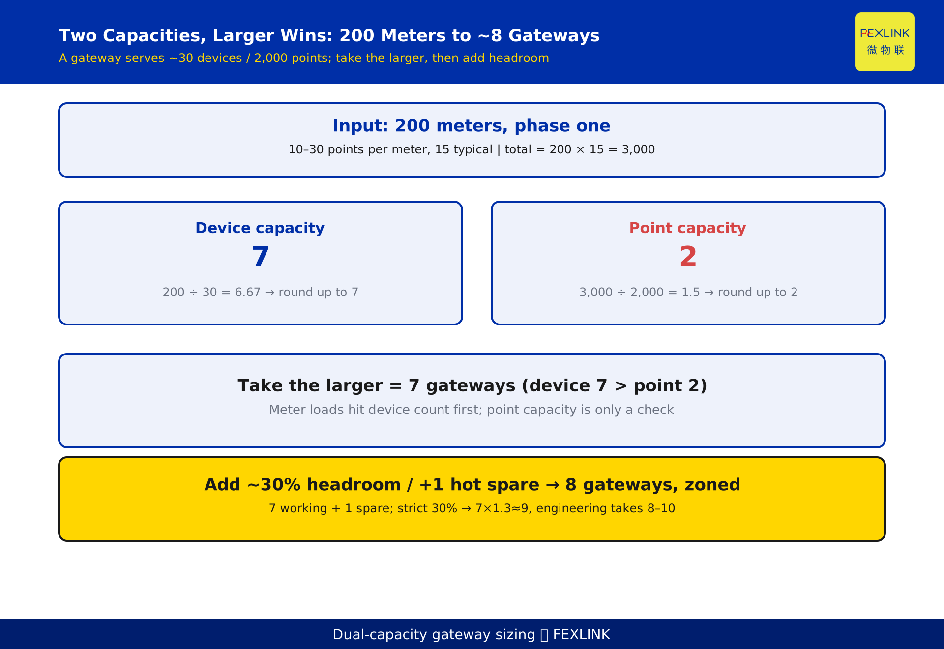
When a campus phase-one rollout brings 200 meters onto a platform, the number of edge gateways cannot be guessed. Size by the larger of two capacities: device count and data-point count. A single gateway typically serves about 30 devices and carries about 2,000 data points; each meter occupies as many points as the parameters it reports (voltage, current, power, energy, harmonics, roughly 10–30 points). Sum the points, divide by the gateway capacity, round up, then add about 30% headroom. For 200 meters that means about 8 gateways deployed in zones. Too few and data stalls; too many and budget burns — and you only discover one gateway polling 60 meters cannot refresh the platform at acceptance.
1. Why gateway count is a calculated problem
A campus phase-one project that lands one or two hundred meters on a platform usually fails in one of two ways. The first is the "one gateway per 60 meters" rule of thumb: at acceptance a single gateway polls 60 meters, Modbus timeouts pile up, and the platform stops refreshing. The second is deciding on device count alone — 200 ÷ 30 ≈ 7 gateways — without counting points; if each meter reports many parameters, the gateway's 2,000-point ceiling is hit first.
Too few gateways means stalled data; too many means wasted budget. Both end in a failed acceptance or an overrun. The correct starting point is to treat "how many devices" and "how many data points" as two independent hard constraints and take the larger.
2. Two capacities: device count and data-point count
A single gateway has two concurrent ceilings: a device count (how many meters it hangs) and a data-point count (how many variables it collects). They are independent; whichever is hit first decides the limit.
- Device capacity: total devices ÷ gateway device capacity (about 30), rounded up.
- Point capacity: total data points ÷ gateway point capacity (2,000), rounded up.
- Take the larger of the two as the working gateway count.
Why take the larger rather than add? One gateway is bound by both constraints at once, yet every meter needs both a device slot and several data points. Whichever capacity fills first makes that gateway overflow. Counting devices only underestimates (point overflow); counting points only overestimates (empty device slots). Taking the larger gives the most conservative, safest floor.
3. How to estimate points per meter: voltage / current / power / energy / harmonics = 10–30 points
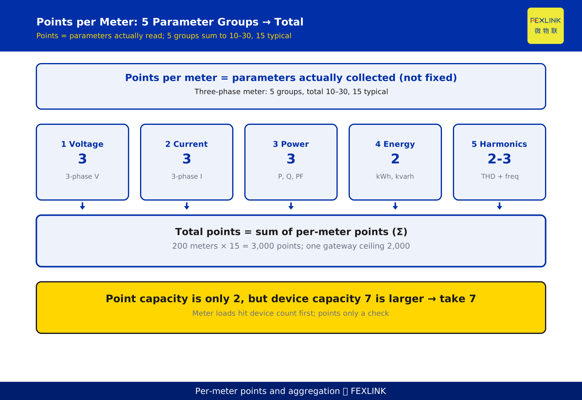
The points a meter occupies equal the number of parameters it actually reports, not a fixed value. For a three-phase smart meter:
- Voltage: three phase voltages = 3 points.
- Current: three phase currents = 3 points.
- Power: active power, reactive power, power factor = 3 points.
- Energy: active energy, reactive energy = 2 points.
- Harmonics and frequency: voltage/current THD plus frequency = 2–3 points.
That totals 13–14 points; adding temperature, leakage, demand and the like can reach 20–30 points. Engineering practice typically assumes 15 points, within the 10–30 band. Note that these 15 points are "the register variables polled by the platform", not "the meter's built-in functions" — the same meter occupies as many points as the registers the platform reads. That is why an identical meter occupies twice the points on two different platforms.
4. Using the 30 devices / 2,000 points fully: capacity is two constraints
A single gateway serving about 30 devices and 2,000 points is two independent ceilings, not "30 devices AND 2,000 points must both be full before it tops out". For meter-type loads — many devices, few points each — the device count almost always fills first: 30 meters × 15 points = 450 points, far below 2,000. So the gateway count is driven by devices, and the point capacity is usually only a check.
Conversely, when the load is PLCs or HVAC controllers — few devices, dense points each — the point capacity takes over. A quick test: compute the average points per device; if it is below 2,000 ÷ 30 ≈ 67 points per device, devices dominate; if above, points dominate.
5. Five steps to the gateway count: total points → divide by capacity → round up → add headroom → zone
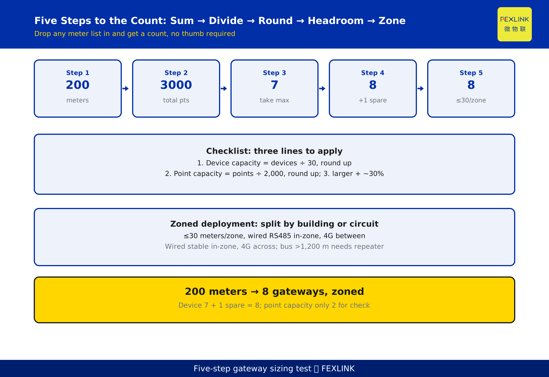
Turn the logic into a five-step test:
- Count total devices: 200 meters in this example.
- Count total points: 200 × 15 = 3,000 points (or sum each meter's actual parameters).
- Take the larger: device capacity 200 ÷ 30 = 6.67 → 7 gateways; point capacity 3,000 ÷ 2,000 = 1.5 → 2 gateways; larger = 7.
- Add about 30% headroom: 7 gateways plus 1 hot spare (about 15%, the lower edge of the 30% experience band) gives 8; at a strict 30% it is 7 × 1.3 ≈ 9, and engineering often lands on the cost-effective point in the 8–10 band.
- Deploy in zones: split by building or circuit, at most 30 meters per zone, with wired RS485 aggregation inside a zone and 4G fill-in between zones.
The test is reversible: any meter list dropped in yields a gateway count, no thumb required.
6. A worked example: 200 meters on a campus
The following is a constructed example used to illustrate the method; it represents no real customer or project. A campus phase-one deployment installs 200 three-phase smart meters, each typically reporting 15 data points (voltage 3, current 3, power 3, energy 2, harmonics and frequency 2, plus temperature 1, total 14–15).
- Total devices = 200; total points = 200 × 15 = 3,000.
- Device capacity: 200 ÷ 30 = 6.67 → round up to 7 gateways.
- Point capacity: 3,000 ÷ 2,000 = 1.5 → round up to 2 gateways.
- Larger = 7; add 1 hot spare (about 30% headroom in practice) for a total of 8 gateways.
- Deployment: split into 8 buildings or 8 circuits, about 25 meters per zone on one gateway (the CW-C1 industrial gateway with multi-port RS485 aggregation), and use 4G links for remote or cross-building weak-signal zones.
Verification: 8 × 30 devices = 240 device slots ≥ 200, leaving 40 slots (20% headroom); 8 × 2,000 points = 16,000 points ≥ 3,000, with points to spare. Both capacities are satisfied, so acceptance is unblocked.
7. Zoned deployment and 4G vs wired choice
More gateways is not better; the key is zoning so each gateway's polling domain stays controllable.
- Wired (RS485 / Ethernet): meters in the same switchroom or building are aggregated over multi-port RS485 to one gateway — stable link, zero traffic cost, the first choice.
- 4G / wireless: meters scattered across buildings, in weak-signal or temporary spots, backhaul over 4G — saves cabling but incurs traffic cost, used for fill-in.
Test: if meters within a zone are physically closer than 100 meters and on the same distribution circuit, prefer wired; if cross-building or uncableable, go 4G. Thirty meters per gateway is the safe value for wired scenarios; for 4G, drop to 15–20 meters to control latency. Do not save a gateway by stretching an RS485 bus — beyond 1,200 meters a repeater is required and the cost exceeds simply adding another gateway.
8. How this splits from "Campus metering retrofit design" (KD-0479)
KD-0479 covers the whole retrofit design: metering-point planning, wiring renovation, construction and acceptance across the full chain. This article covers one sub-problem — how to size gateway capacity. The increment is the dual-capacity sizing method: it splits "how many devices" and "how many points" into two independent constraints, takes the larger, and gives an applicable five-step test.
After reading KD-0479 and obtaining the meter list, apply this article's method to compute the gateway count directly, then return to KD-0479's deployment framework to place them. The two are a whole-to-part relationship, not an overlap.
9. How the related products land
Once the count is known, gateway selection follows interfaces and links. The ESX-0223-GR edge computing gateway supports multi-port RS485 collection and can run 4G and wired links simultaneously, fitting the zoned aggregation main gateway. The CW-C1 industrial gateway focuses on multi-port RS485 aggregation at high cost-effectiveness, suiting meter-dense switchrooms. The CW-C2 / CW-C3 industrial gateways offer flexible 4G and wired combinations, suiting scattered fill-in points.
Selection test: same-zone wired prefers CW-C1, cross-zone fill-in uses CW-C2 / CW-C3, and aggregation points needing edge compute (local pre-processing, resumable transfer) use ESX-0223-GR. The three are combined by zoning role — no model stacking, no waste.
10. FAQ
Q: Can I size on device count alone and skip points?
No. Meter-type devices have few points each, so devices dominate and points are only a check; but PLCs, controllers and harmonic-capable meters are point-dense and the point capacity fills first. Counting devices only underestimates the gateway count, and after go-live the points overflow and refresh stalls. Taking the larger is what is safe.
Q: Where does "30 meters per gateway" come from, and can it be beaten?
Thirty is a safe RS485 polling rule of thumb, bound by bus length, baud rate and polling period together. In a dense zone with a long polling period it can stretch to 40–50 meters; in 4G scenarios, drop to 15–20 meters for latency. Treat it as the anchor for the lower capacity bound, not a fixed number.
Q: Is 2,000 data points also fixed?
Two thousand is a reference ceiling for a single gateway's collection channel; it is a customizable item, and the exact limit follows the selection manual per model. The method is unchanged: total points ÷ gateway point ceiling, rounded up. The 2,000 here is an illustrative example; the product knowledge base is authoritative.
Q: After adding 30% headroom the numbers do not close — how many exactly?
The larger gives 7; headroom is an experience band (about 15%–30%). Engineering often takes 7 working plus 1 hot spare = 8 as the cost-effective point; at a strict 30% it is about 9–10. The value depends on how much you want to reserve for failover and expansion — it is not a single-choice question.
Q: After zoning, how many meters per gateway is most stable?
For wired same-zone scenarios, 20–30 meters is most stable; for 4G, 15–20. The test is the polling period: if data must refresh every 1 minute, keep the per-gateway meter count low; at a 5-minute cadence it can relax. Set the refresh rate first, then back-calculate the per-gateway meter count.
Scope and limitations
- The gateway sizing method discussed here applies to edge-gateway planning where meters, PLCs and controllers are polled over RS485 / Modbus and similar; non-polling access (such as direct TCP streams) uses a different capacity model and must be accounted separately.
- The figures "about 30 devices and 2,000 data points per gateway" are constructed reference values to illustrate the dual-capacity method; they are customizable items, and the exact ceiling follows the selection manual and product knowledge base for the specific model. This article makes no selection commitment.
- The per-meter point count (10–30) depends on the registers actually collected; an identical meter can differ by a factor of two across platforms. The 15 points used here is a typical estimate, not a fixed value.
- The example parameters are constructed to explain the method, are marked as examples, and represent no real customer or project; the actual gateway count must be computed on site from the meter list, circuit layout, refresh rate and link budget.
- Descriptions of the related products (ESX-0223-GR edge computing gateway, CW-C1 / C2 / C3 industrial gateways) follow the latest selection manuals; this article only suggests roles within the access architecture.
- Industry-common practices referenced here (such as RS485 bus length and polling period) follow current standards and field measurements; no specific metering accuracy class or certification conclusion is provided.
Frequently Asked Questions
Hundreds of Meters to the Platform
When a campus phase-one rollout brings 200 meters onto a platform, the number of edge gateways cannot be guessed