 FEXLINK Research Institute
The short answer
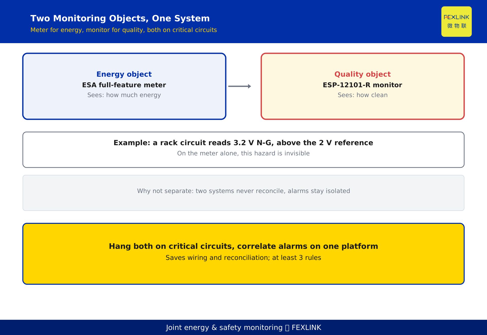
A data-center cabinet must monitor two things at once: energy (how much electricity is used) and power quality (how clean the electricity is). A meter alone sees only the first; a neutral-to-ground (N-G) overvoltage at the UPS output often goes unnoticed until it destroys equipment. Build one system: a zero-ground monitor watches power quality, a full-feature meter watches per-circuit energy, and an edge gateway converges both. On critical circuits hang both devices, send their data to one platform with correlated alarms — cheaper in wiring and reconciliation than two standalone systems.
1. Two objects in one cabinet
Two completely different classes of information flow through a data-center distribution cabinet.
The first is the energy object: how many kWh each circuit draws, its real-time power, and its monthly peak demand. This answers "how much electricity and money" and underpins efficiency management and billing.
The second is the power-quality object: is the neutral-to-ground voltage high, how much harmonic content is in the voltage, are the three phases balanced, is the voltage deviation within limits. This answers "is the electricity clean, will it damage equipment" and belongs to electrical safety.
These two are often split into two separate systems: energy collected by meters, power quality by dedicated analyzers. The problem is exactly there — the two systems operate independently, their data never reconciles, their alarms are isolated, and operators flip between two screens, slowly and easily missing the real hazard.
2. Why N-G voltage is a data-center-specific pain
Neutral-to-ground voltage (the potential between the neutral and protective earth) is rarely singled out in ordinary civil distribution, yet it is a frequent hidden risk in data centers.
IT equipment switching power supplies are high-frequency non-linear loads. At the UPS output they inject large harmonic currents into the neutral; when the neutral current cannot cancel across the three phases, the neutral-to-earth potential is pushed up continuously, manifesting directly as rising N-G voltage. Once N-G voltage exceeds what the equipment power module can tolerate, it causes spurious reboots and packet loss at best, and destroys interface chips at worst, breaking the service.
Important note: there is no single mandatory national GB limit on N-G voltage margin. Different vendors state their own reference ceilings in their equipment specifications; a 2 V-level reference threshold is common in practice. This article gives no fixed national-standard number; real projects should follow the equipment specification or the data-center design code.
3. How UPS harmonics and unbalance push N-G voltage up
To trace the cause you must understand the physical chain that raises N-G voltage.
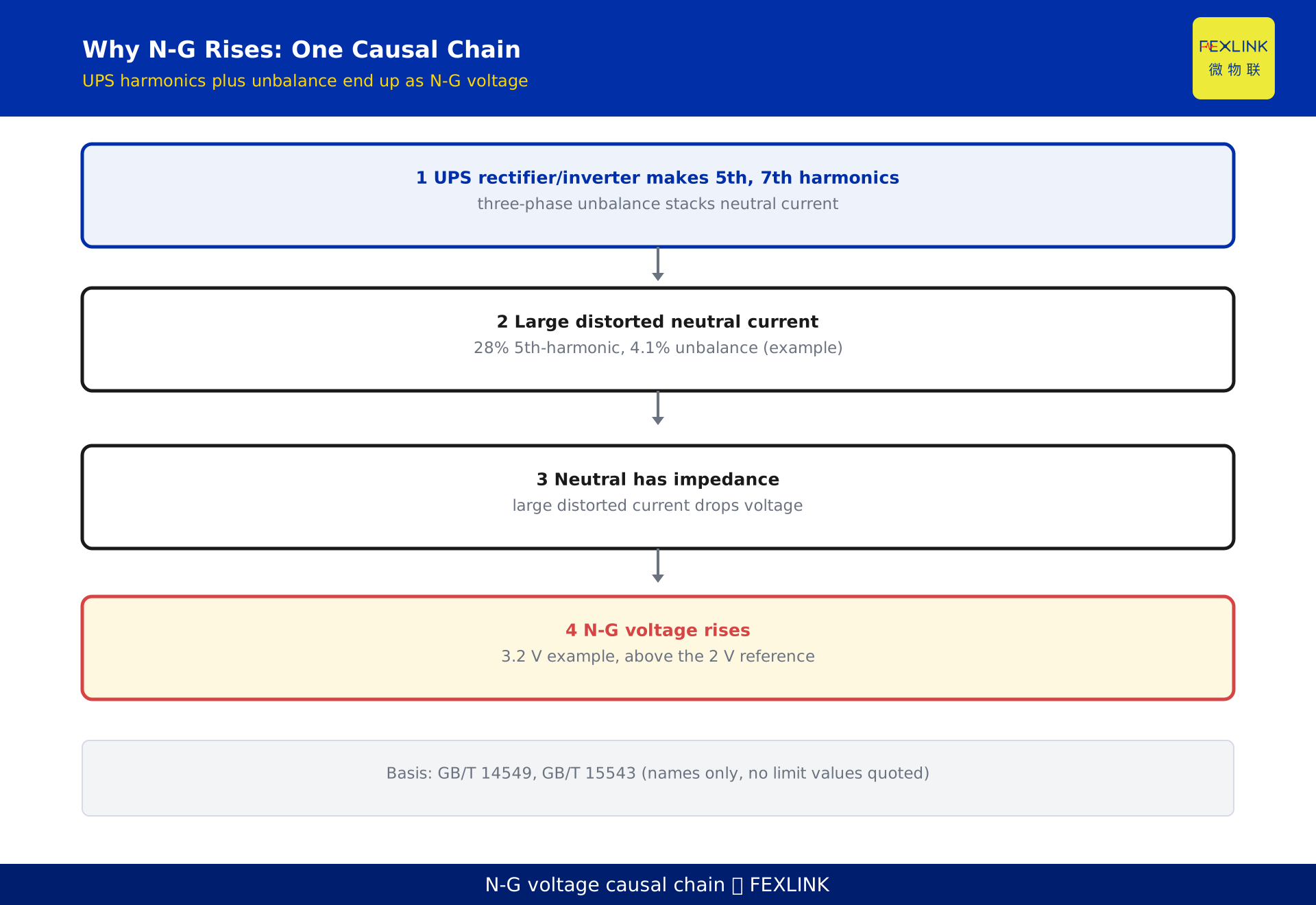
The UPS generates harmonics at both its rectifier and inverter stages, dominated by low-order odd harmonics such as the 5th and 7th. When the three-phase load is unbalanced, the neutral current equals the sum of the un-cancelled zero-sequence components and, in the extreme, its amplitude can approach or even exceed the phase current. Harmonics stacked on unbalance make the neutral current both distorted and large.
The neutral has impedance — line resistance, transformer winding resistance, and connection contact resistance. A large distorted current produces a voltage drop across this impedance, and that drop is the main source of N-G voltage. The chain: UPS switching harmonics plus three-phase unbalance produce a large, distorted neutral current; that current drops voltage across the neutral impedance; the result is a higher N-G voltage.
The two relevant standards here are GB/T 14549 (power quality — harmonics in public supply networks) and GB/T 15543 (power quality — three-phase voltage unbalance). They are the basis for judging whether harmonics and unbalance exceed limits. This article cites the standard names only and does not quote their numeric limit values.
4. Where to place the monitor
The ESP-12101-R zero-ground voltage monitor is placed along the power-quality sampling points.
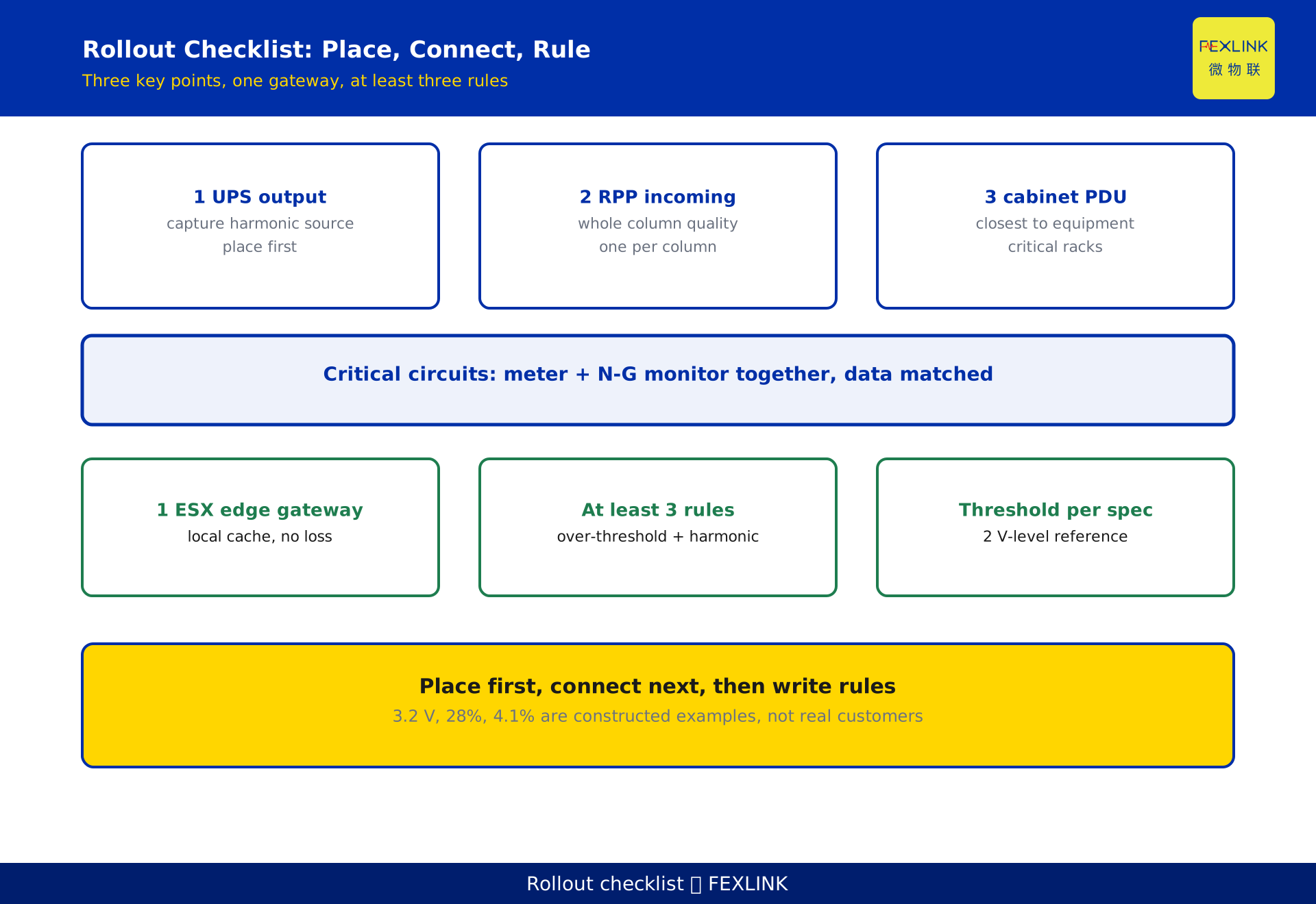
Prioritize three locations: the UPS output, the column-header cabinet (RPP) incoming side, and the critical cabinet PDU incoming side. The reason is direct — N-G problems mostly occur at the UPS output and the terminal distribution; the upstream busbar shows nothing. The UPS output captures the source signature of harmonics and unbalance; the RPP reflects the quality delivered to a whole column of racks; the PDU is closest to the protected equipment.
Each monitor takes only what it should: N-G voltage is mandatory, with phase voltage and neutral current added when needed to corroborate harmonics and unbalance. It does not replace the meter; it focuses solely on "is the electricity clean."
5. How to place the meters
The ESA full-feature smart meter hangs on circuits such as air conditioning, UPS, lighting, and rack column headers, covering the "how much energy" line.
Its role is divided from the zero-ground monitor: the meter handles energy and basic electrical quantities, the monitor handles power-quality specifics. The two can coexist on the same circuit and even share the gateway's communication link without conflict.
Granularity depends on management needs: core rack columns, high-power air conditioning, and UPS input/output circuits should be covered first; ordinary lighting can be sampled. The point is to make the "energy ledger" and the "quality ledger" match one-to-one by circuit label, so later correlated alarms can be tied to a specific circuit.
6. One gateway for both
The ESX edge computing gateway is what fuses the two systems. It centrally collects data from meters and zero-ground monitors and does three things: local caching so nothing is lost during an outage; timestamp alignment so readings from different devices line up at the same instant; protocol normalization before sending to the platform.
Where does it save over two standalone systems? Most visibly in the communication link: the meter runs on one bus, the monitor on another, which used to mean two gateways and two reconciliations. Now a single ESX gateway is shared, with fewer wires, and the data naturally lands in one table — operators no longer hand-stitch two systems' reports.
7. Correlated alarms: let the two confirm each other
An isolated N-G alarm is easy to false-trigger — the neutral current is intrinsically more complex than the phase current. The value of correlation is to let "energy" and "quality" confirm each other.
A constructed example, not a real customer: a cabinet circuit's zero-ground monitor reads 3.2 V, above the 2 V reference ceiling in that equipment's specification; at the same time the same circuit's full-feature meter shows a 5th-harmonic content of 28% and a three-phase unbalance of 4.1%. The three numbers appear together, and the platform automatically ties the alarm to "a certain phase at the UPS output" instead of throwing a lone "N-G high."
This "quality anomaly plus energy signature" dual-condition trigger is more accurate than a single condition and locates the root-cause circuit more easily. Emphasis: the 3.2 V, 28%, and 4.1% above are constructed example values to illustrate the correlation logic and represent no real project.
8. Common mistakes
Mistake one: the meter can read N-G voltage on the side. An ordinary energy meter does not measure the N-G voltage; a dedicated monitor such as the ESP-12101-R is required.
Mistake two: high N-G voltage means the UPS is broken. Most often it is wiring, harmonics, and unbalance combined — not the UPS failure rate. Check load balance and wiring before suspecting the equipment.
Mistake three: two separate systems are fine. Without correlation, alarms stay isolated and location always depends on manually flipping between screens; by the time you reconcile, the point of "joint monitoring" is already lost.
9. Rollout checklist
A decision checklist you can execute:
- On critical circuits hang both the meter and the monitor; prioritize UPS output, RPP, and core cabinet PDU.
- Use one ESX edge gateway to converge everything, with local caching so data survives outages.
- Write at least three correlation rules on the platform, e.g. N-G over threshold plus harmonic distortion, N-G over threshold plus unbalance, and escalation only after consecutive breaches.
- Set thresholds per the equipment specification or data-center design code, written into documents, not by word of mouth.
- Monthly, review alarm-to-energy correlation to verify the correlation actually locates the circuit.
FAQ
Q: How high is too high for N-G voltage?
There is no single mandatory national GB limit; a 2 V-level reference ceiling is common in equipment specifications. Follow your specific equipment's specification or the data-center design code — this article gives no fixed national-standard number.
Q: Can an ordinary smart meter read N-G voltage directly?
No. N-G voltage is the potential between neutral and protective earth; an ordinary energy meter has no such measurement channel. A dedicated zero-ground monitor such as the ESP-12101-R is needed.
Q: The UPS output has high harmonics — should I replace the UPS?
Not necessarily a hardware problem. The UPS rectifier and inverter switching inherently produce 5th and 7th harmonics, and three-phase unbalance amplifies the neutral current. Check load balance and wiring before judging whether mitigation is needed.
Q: After merging the two systems, will the data be less reliable?
The opposite. One edge gateway converging and timestamp-aligning the data makes it land naturally in one table, less prone to mismatch than two systems each reconciling separately; the gateway's local cache also guarantees no loss during outages.
Q: How many correlation rules are enough?
At least three: N-G over threshold with high harmonic distortion, N-G over threshold with high unbalance, and escalation only after consecutive breaches. Too few causes false alarms; too many adds operator burden.
Scope and limitations
This solution targets the "energy plus electrical safety" joint monitoring of data-center distribution cabinets, centered on the coordinated placement and correlation of a zero-ground monitor, a full-feature meter, and an edge gateway. The 3.2 V, 28%, and 4.1% figures are constructed examples to illustrate the correlation logic and represent no real customer or project. The N-G voltage margin follows the equipment specification or data-center design code; this article provides no fixed national-standard limit. Judgment of harmonics and unbalance rests on GB/T 14549 and GB/T 15543 in their current editions; this article cites the standard names only and quotes no limit numbers. Function descriptions of the ESA, ESP, and ESX product families follow the latest selection manuals and product knowledge base, and this article is not a selection or procurement recommendation.
Frequently Asked Questions
How high is too high for N-G voltage?
There is no single mandatory national GB limit; a 2 V-level reference ceiling is common in equipment specifications. Follow your specific equipment's specification or the data-center design code — this article gives no fixed national-standard number.
Can an ordinary smart meter read N-G voltage directly?
No. N-G voltage is the potential between neutral and protective earth; an ordinary energy meter has no such measurement channel. A dedicated zero-ground monitor such as the ESP-12101-R is needed.
The UPS output has high harmonics — should I replace the UPS?
Not necessarily a hardware problem. The UPS rectifier and inverter switching inherently produce 5th and 7th harmonics, and three-phase unbalance amplifies the neutral current. Check load balance and wiring before judging whether mitigation is needed.
After merging the two systems, will the data be less reliable?
The opposite. One edge gateway converging and timestamp-aligning the data makes it land naturally in one table, less prone to mismatch than two systems each reconciling separately; the gateway's local cache also guarantees no loss during outages.
How many correlation rules are enough?
At least three: N-G over threshold with high harmonic distortion, N-G over threshold with high unbalance, and escalation only after consecutive breaches. Too few causes false alarms; too many adds operator burden.