 FEXLINK Research Institute
The short answer
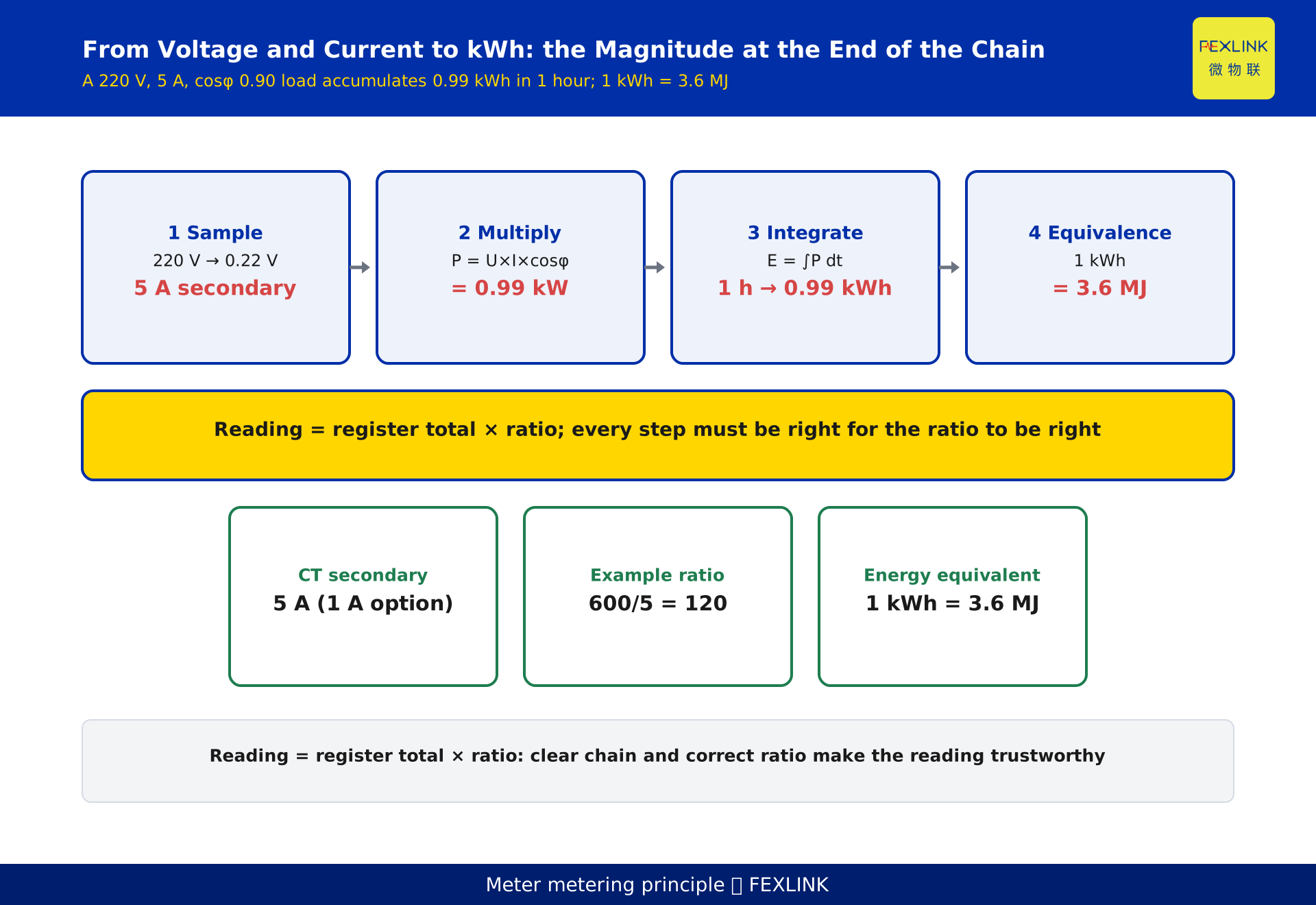
A meter does not "read" its number; it computes it. Inside sits a chain of sample → multiply → integrate. A divider and a current transformer (CT) scale the grid's high voltage and high current down to small signals a chip can handle (heavy-current circuits normally pass through a 5 A secondary). The metering chip multiplies each instantaneous voltage and current sample, giving instantaneous power P = U·I·cosφ, then integrates over time to accumulate energy; the kilowatt-hours in the register are what the display prints. Ratio, transformation ratio and error all live on this chain — understand it and the reading, the ratio and the error all make sense.
1. The whole chain at a glance: sample, multiply, integrate
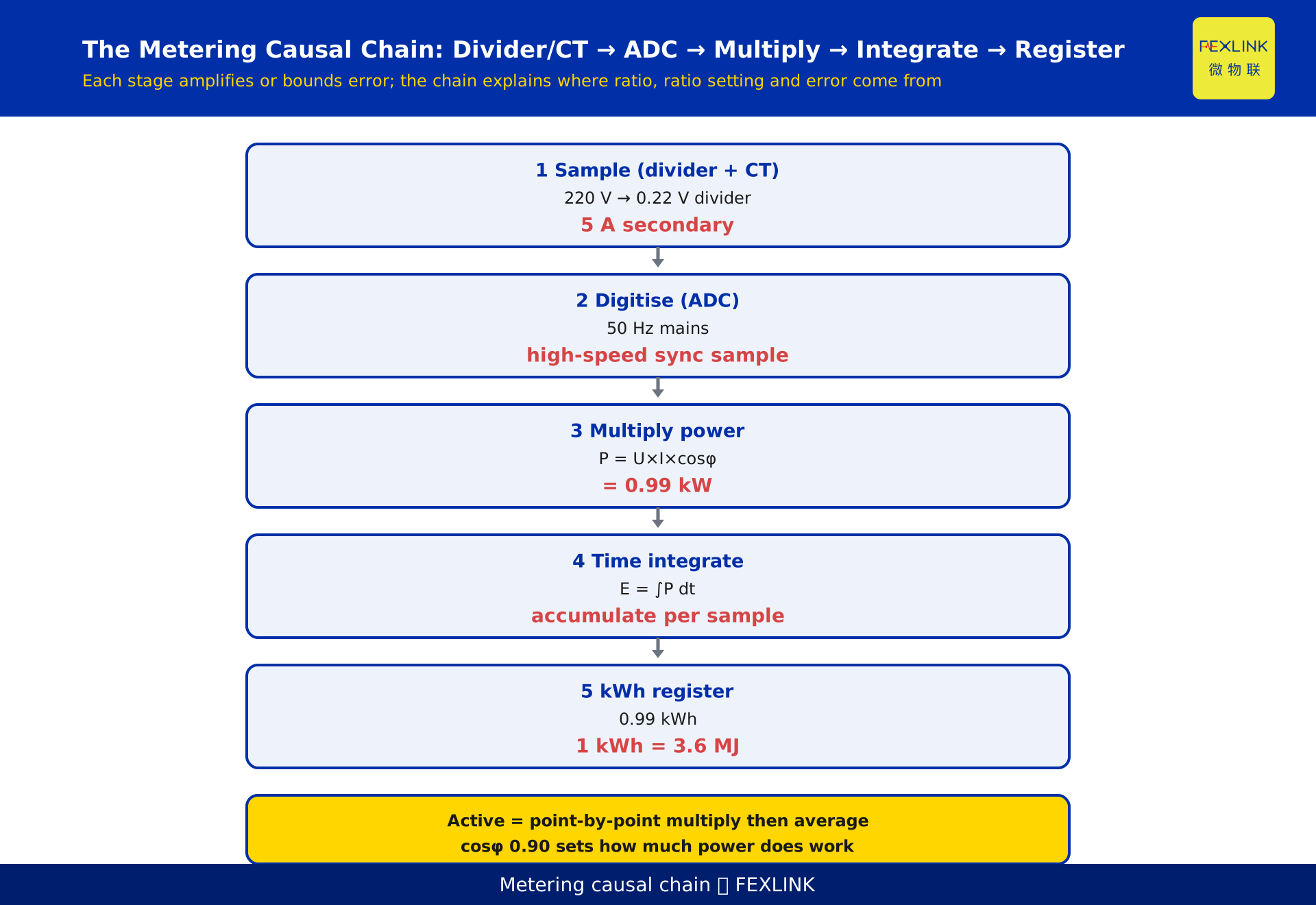
Most people only recognise the cumulative kilowatt-hours on the screen. But the real job of a meter is to integrate "power at this moment" over "time". The grid's voltage and current are alternating quantities of hundreds of volts and hundreds of amps; they cannot go straight into a low-voltage digital chip for multiplication and must be scaled first. The metering chain splits into four stages:
- Sampling — voltage via a divider resistor, current via a current transformer (CT), both scaled down proportionally to small signals.
- Digitising — an ADC turns the scaled analogue quantities into a stream of time-stamped digital samples.
- Multiplying — the metering chip multiplies each pair of voltage and current samples taken at the same instant, yielding instantaneous power.
- Accumulating — that instantaneous power is integrated over time into energy and written into an accumulating register.
Later concepts — ratio, transformation ratio, sources of error — and the companion piece on reading nameplate ratios all hang on this chain.
2. Divider and CT: why the big signal must become a "small signal"
A chip can only compute over a limited voltage and current range, typically a few volts and a few amps. The incoming voltage may be 220 V or 380 V and higher; current easily passes 100 A. Feeding that straight in would destroy the chip and exceed its quantisation range.
- Voltage side uses resistive division: a string of precision resistors drops 220 V by a fixed ratio (for example 1/1000) to around 0.22 V before the ADC.
- Current side uses a current transformer (CT): the primary is in series with the circuit, and the secondary delivers a small current proportional to the primary. In power systems the standard secondary rated current of a CT is 5 A (1 A in some settings), so whatever the primary, the secondary is held within that range, then scaled back by the ratio.
The transformation ratio is primary current ÷ secondary current. Two ratios constructed for illustration: 100/5 = 20 and 600/5 = 120. So a 600 A primary circuit fitted with a 600/5 CT still has a 5 A full-scale secondary; at a primary of 480 A the secondary is about 4 A. The chip computes that 4 A, then multiplies by 120 to recover the 480 A primary. That "multiply back" step is where the ratio later comes from.
3. Inside the metering chip: how instantaneous power is multiplied out
After sampling, the key operation is multiplication. Inside the chip is a high-speed digital path: the ADC samples voltage and current simultaneously at a rate well above the 50 Hz mains frequency, producing two aligned sample streams. The chip multiplies each pair of samples taken at the same instant:
instantaneous power p(t) = u(t) × i(t)
Computing only U×I (rms values) gives apparent power, with no phase. The meter wants active power, which keeps the waveform and multiplies point by point then averages. Mathematically:
active power P = U × I × cosφ
where cosφ is the cosine of the voltage-current phase difference, the share of power that actually does work. A lower cosφ means less of the same current "does the job", raising line loss and idle draw. Example: a 220 V, 5 A, cosφ 0.90 load gives 0.99 kW; over 1 hour that is 0.99 kWh. The chip's internal operation is this point-by-point multiply then average, not a product of two rms values.
4. Active, reactive, apparent: how the chip tells them apart
From one voltage and one current, the chip can separate three power quantities by how it handles phase:
- Apparent power S = U × I — ignores phase, only the scale of the product.
- Active power P = U × I × cosφ — point-by-point product then average; the billed, working part.
- Reactive power Q = U × I × sinφ — tied to the 90° phase component; does no direct work but occupies line and transformer capacity.
The bill is settled on active energy, so the chip's core output is the time integral of active power. Reactive energy is not billed, but a low cosφ triggers a power-factor charge and magnifies line loss. This explains a common puzzle: the disk turns yet the bill is "not as big as the current suggests" — only the active share is counted.
5. From instantaneous power to kWh: time integration and the accumulator
Instantaneous power is a "now" quantity, in kilowatts. The bill settles a "cumulative over time" quantity, in kilowatt-hours. Between them sits one integral:
energy E = ∫ P dt
Inside the chip is an accumulating register: each sampling period it takes the just-computed instantaneous power, multiplies by the period length (a millisecond-scale Δt), and keeps adding the result. Over time the number in the register is kilowatt-hours. The "12345.6 kWh" on screen is merely a formatted print of that register.
Here too is the physical equivalence: 1 kWh = 1 kW sustained for 1 hour, equivalent to 3.6 MJ. The kilowatt-hours a meter accumulates are, at root, accumulated energy.
6. Ratio and transformation ratio: the multiplication behind the reading
Why does a reading sometimes "miss the real value by several times"? The root is the ratio setting. The chip computes power for the small secondary current; to recover the true primary consumption it must multiply by the ratio. Hence:
displayed energy ≈ register total × ratio (primary ÷ secondary)
Two ratios constructed for illustration: 100/5 = 20 and 600/5 = 120. If the field unit is a 600/5 CT but the meter is mistakenly set to 100/5, then for the same secondary current the meter under-multiplies by a factor of 6 — the reading is only 1/6 of the true value, a 6× discrepancy. This kind of error never alarms; it quietly bends every conclusion downstream.
So the ratio is not some mystical "meter magnification"; it is the explicit primary÷secondary conversion at the chain's final step.
7. Where error comes from: every stage can drift
Even an ideal chain meets real error, and every segment contributes:
- Sampling — divider resistor drift, CT ratio and phase errors, and ADC quantisation noise make the scaled signal itself inaccurate.
- Multiplying — if samples are not strictly time-aligned, the instantaneous power is off.
- Integrating — clock drift makes Δt wrong, and over time the kWh shifts.
National standards such as GB/T 17215 and IEC 62053-21 give a framework for accuracy classes and test methods of electricity meters, but the specific error limits and class values follow the current effective edition, the manufacturer's manual and the verification regulation; this article states no fixed limits. The right way to judge "is this meter accurate" is to send it for verification per the regulation, not to apply a limit copied from the web.
8. An engineering view: verifying metering in a campus retrofit
In one campus power-distribution upgrade, circuit-level metering points were added. At handover the crew reported "the main incomer energy is far larger than the sum of the branches — the meters must be faulty". On-site checking showed the meters were fine; the fault was the ratio. The main incomer used a 600/5 CT, but some branch meters were set to 100/5, so those branches read systematically low and the totals could not close.
The verification had three steps. First, read the CT nameplate to confirm the primary/secondary ratio (here 600/5 = 120). Second, enter the meter settings and check ratio, phase sequence and connection group. Third, use a clamp meter on the secondary, back-calculate the primary, and compare with the display. After the three steps the discrepancy vanished and main and branches closed again.
This kind of endpoint metering maps to the FEXLINK ZSA embedded multi-function smart meter (divider, CT sampling and metering chip integrated on one board, suited to embedded and compact installs) and the ESA all-element smart meter (circuit-level full-element metering, paired with the digital electrical intelligent supervision system). They secure the premise that sampling and ratio are correct; whether main and branches close depends on whether ratio, phase sequence and wiring were checked on site.
9. How to read a kWh without stepping on a rake: the field checklist
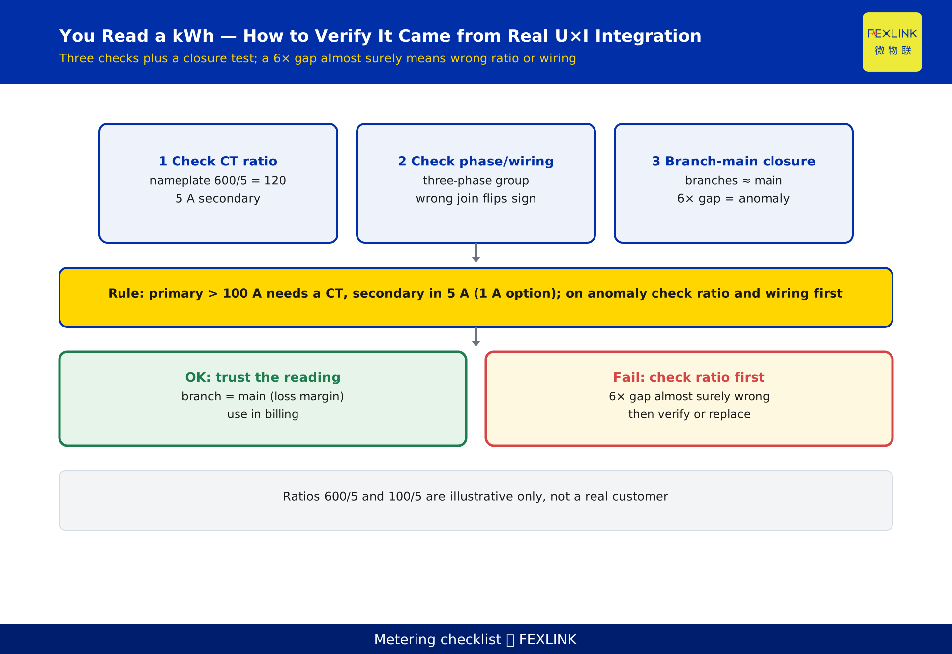
Given a kilowatt-hour reading, to judge whether it truly came from "voltage × current, then integrated", walk this checklist:
- Check the CT ratio — nameplate primary/secondary ratio matches the meter setting; the secondary rated falls in the 5 A (or 1 A) range and the measured value does not exceed it.
- Check phase sequence and connection group — three-phase meters especially must confirm these; a wrong connection directly changes the power sign and value.
- Run a main-branch closure test — over the same period, branch kWh should roughly equal main kWh (allowing normal loss); a several-times gap almost certainly means a wrong ratio or wiring.
- Separate active from reactive — confirm the screen shows active energy; for power factor, read reactive and cosφ separately.
One criterion: when the primary current exceeds about 100 A, fit a CT so the secondary sits in the 5 A range, and choose a ratio so the secondary at maximum load is not below about 1 A (a 1 A rated secondary is an option); on an anomalous reading, check ratio and wiring first.
10. FAQ
Q: How exactly does a meter turn voltage and current into a bill?
Internally it runs sample → multiply → integrate: the divider and CT shrink the big signals, the metering chip multiplies each voltage and current sample into instantaneous power, integrates over time into kilowatt-hours, then converts to money at the tariff. The reading is computed, not directly measured.
Q: What is a CT for, and why is the secondary 5 A?
A CT scales a large current circuit down to a small current so the chip can handle it safely. In power systems the standard CT secondary rated current is 5 A (1 A versions exist), meaning whatever the primary, the secondary is held within that range and recovered to primary by the ratio.
Q: What are ratio and transformation ratio, and why can a reading differ severalfold?
The ratio is primary current ÷ secondary current (e.g. 600/5 = 120). The chip computes power for the small secondary current and must multiply by the ratio to recover true primary consumption. If the meter's ratio is set wrong (say 20 where 120 belongs), the reading is systematically low by several times.
Q: What is the difference between active, reactive and apparent power, and which is billed?
Apparent S = U×I is the scale; active P = U×I×cosφ is the working, billed part; reactive Q = U×I×sinφ does no direct work but occupies capacity. The bill settles on active energy; a low cosφ triggers a power-factor charge and magnifies line loss.
Q: Two meters disagree — what is the most likely cause?
Usually not a faulty meter but mismatched ratio, phase sequence or connection group: CT nameplate disagrees with meter setting, a three-phase connection is miswired, or main and branch use different ratio bases. Run a main-branch closure test and a ratio check before judging whether verification is needed.
Scope and limitations
- This article explains the general "sample — multiply — integrate" chain of an AC active energy meter, useful for understanding meters and smart meters in residential, commercial and industrial settings. DC metering and harmonic-energy metering are out of scope.
- The CT standard secondary rated current of 5 A (and 1 A) quoted here is a common power-system rating; CT selection, ratio and accuracy class for a specific project follow the design drawings and current standards. The ratio examples (100/5 = 20, 600/5 = 120) and the campus scenario are constructed to illustrate the point and represent no real customer or project.
- The core physical relations P = U·I×cosφ, energy E = ∫ P dt, and 1 kWh = 3.6 MJ are general engineering relations and may be cited freely.
- The standard numbers referenced (GB/T 17215, IEC 62053-21) are mentioned only as a framework; they must not be used to infer specific edition numbers, clause numbers or error limits. Specific accuracy classes and error limits follow the current effective edition, the manufacturer's manual and the verification regulation.
- The models, parameters and functions of the ZSA embedded multi-function smart meter, the ESA all-element smart meter and the digital electrical intelligent supervision system follow the latest selection manual and product knowledge base; this article is not a selection or procurement recommendation.
- Any coefficient not in the verified fact base is stated here as "per current standard / measured value", and no fixed figure has been invented.
Frequently Asked Questions
How Does a Meter Turn Voltage and Current into kWh
A meter does not "read" its number; it computes it. Inside sits a chain of sample → multiply → integrate