 FEXLINK Research Institute
The short answer
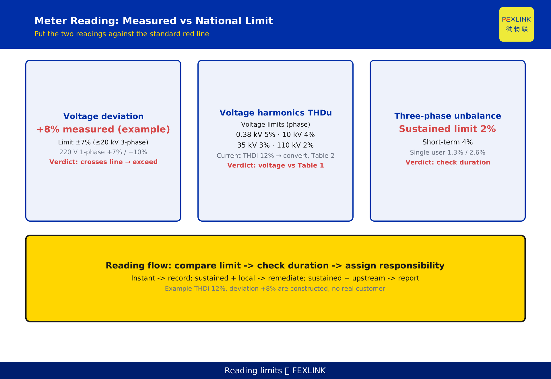
Most percentages the meter prints every day are normal fluctuations; only those that touch a national-standard limit count as "exceeding". Three hard red lines: voltage deviation ±7% (GB/T 12325), voltage harmonic THDu by voltage class — 5% at 0.38 kV, 4% at 6–10 kV, 3% at 35 kV (GB/T 14549), and three-phase unbalance 2% for normal operation, 4% for short durations (GB/T 15543). The reading logic has three steps: first compare against the limit, then check the duration, finally assign responsibility. An instantaneous excursion needs no action; only a sustained one justifies a remediation project. The example figures are constructed to illustrate the logic and represent no real customer.
1. What the two readings actually measure
The two readings in the title measure two completely different things.
THDi is the total current harmonic distortion — how much non-linear loads (VFDs, rectifiers, arc furnaces, LED supplies) pollute the current with harmonics. Voltage deviation is the percentage offset of the measured voltage from the nominal voltage — for a nominal 380 V three-phase system, a reading of 410 V means a deviation of +7.9%.
Neither number by itself equals "exceeding". THDi must be judged against the harmonic current allowable table in GB/T 14549-1993 (values by voltage class and reference short-circuit capacity); voltage deviation can be judged directly against the deviation limits in GB/T 12325. The THDi 12% and +8% deviation used here are demonstration values representing no real customer or project.
Unlike "how harmonics are computed" (KD-0460, article 460), this article skips FFT/Fourier and answers a practical question: once the number is computed, which line, how long, who owns it.
2. The voltage-deviation red line: how ±7% is set
GB/T 12325-2008 "Power quality — Deviation of supply voltage" sets the limits by voltage class:
- 35 kV and above: the sum of the absolute positive and negative deviations must not exceed 10% of the nominal voltage;
- 20 kV and below, three-phase supply: deviation is ±7% of the nominal voltage;
- 220 V single-phase supply: deviation is +7% / −10% (the lower bound is wider because end-of-line drop is more common);
- Note: when both deviations have the same sign (both positive or both negative), the larger absolute value is taken as the basis.
Back to the example: at nominal 380 V, the reading must exceed 410.4 V (>7%) to touch the red line; +8% has already crossed it. Voltage deviation is a receiving-end metric — long heavy-loaded lines read low, light load reads high — so confirm the measurement point (transformer LV side vs end board) before judging.
3. How to judge harmonics: voltage by THDu, current by the table
GB/T 14549-1993 "Power quality — Harmonics in public supply network" is judged on two levels.
Voltage harmonics THDu can be compared directly to the limit (Table 1, by phase voltage):
| Nominal voltage | Total harmonic distortion THD | Odd-order | Even-order |
|---|---|---|---|
| 0.38 kV | 5.0% | 4.0% | 2.0% |
| 6–10 kV | 4.0% | 3.2% | 1.6% |
| 35–66 kV | 3.0% | 2.4% | 1.2% |
| 110 kV | 2.0% | 1.6% | 0.8% |
Current harmonics THDi cannot be judged by a single percentage: Table 2 gives per-order allowable currents by voltage class and reference short-circuit capacity. A 12% THDi must be converted into the per-order currents injected into the point of common coupling and compared with Table 2 for that order and capacity; because the reference short-circuit capacity differs per connection point, you cannot call "12% exceeds" off-site.
This is the source of many misjudgments: reading THDi off the meter and treating it like a voltage limit inevitably produces a wrong conclusion.
4. Two tiers of unbalance: what 2% and 4% each govern
GB/T 15543-2008 "Power quality — Three-phase voltage unbalance" states that the negative-sequence voltage unbalance at the system point of common coupling:
- must not exceed 2% during normal operation;
- must not exceed 4% for short durations (short duration typically means on the order of 1–3 minutes).
In addition, the unbalance caused by a single customer at the point of common coupling is tighter: generally 1.3%, and 2.6% for short durations. This "responsibility allowance" is the basis for assigning responsibility later — if the local load pushes the coupling-point unbalance above 1.3%, it is likely the local side's responsibility.
Unbalance exceeding the limit usually comes from large single-phase loads concentrated on one phase (such as many single-phase chargers or single-phase heaters) or from uneven three-phase load distribution. It reduces transformer output, raises line losses and overheats motors, but first confirm whether you are looking at the "whole coupling point" or the "local injection".
5. Instantaneous vs sustained excursion: not just the number
Most limits are statistical requirements for "normal operation", not "never exceed for an instant". A welder start-up or capacitor switching makes THDu or deviation jump momentarily — an instantaneous excursion is not non-compliance.
Weight the judgment by duration:
- Occasional instantaneous excursion: record it and move on, no action needed;
- Sustained excursion (persistent or frequently recurring): warrants a remediation project;
- How long counts as "sustained" depends on the metric. The "4% for short duration" for unbalance gives the 1–3 minute order of magnitude; for harmonics and voltage deviation, although no uniform number of seconds is given, engineering practice usually uses a statistical window (such as the 95% probability large value, or a daily/weekly average) crossing the limit as the remediation criterion.
So the same readings — sustained for 8 hours versus a 1-second spike — call for completely different handling.
6. Assigning responsibility: local load or upstream source
The last step of excursion judgment is to decide "whose pot it is".
The national standard assesses the user for the pollution the user injects into the point of common coupling. If the root cause is the upstream source, a neighbouring customer or the grid side, no amount of local mitigation equipment will bring it down.
A practical way to decide: at the point of common coupling, take the main local non-linear loads (drives, rectifiers, arc equipment) offline one by one and watch whether the excursion disappears. If it disappears, the local load caused it and the local side owns it; if not, the source is upstream or external — report to the power dispatcher or negotiate, rather than blindly adding local mitigation.
The single-customer harmonic allowance (the 1.3% / 2.6% analogy for unbalance, harmonics per Table 2) is exactly this quantified boundary of responsibility.
7. The reading flow: compare → duration → responsibility
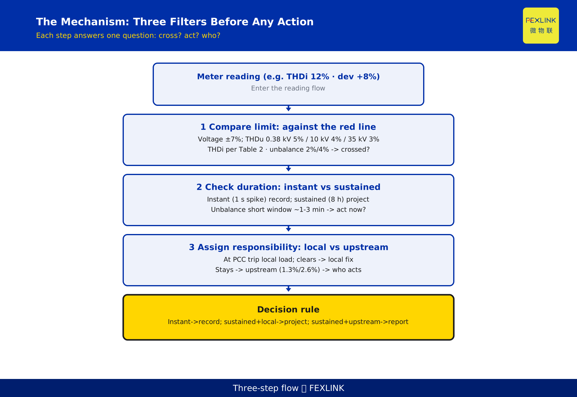
Condense the previous three sections into one executable three-step flow; any reading can be judged by it:
- Compare against the limit: first put the measured value against the standard red line. Voltage deviation against ±7% (or the relevant class), THDu against Table 1 voltage limits, THDi against Table 2 current allowable values (with conversion), unbalance against 2% / 4%. This step answers "did it cross the line".
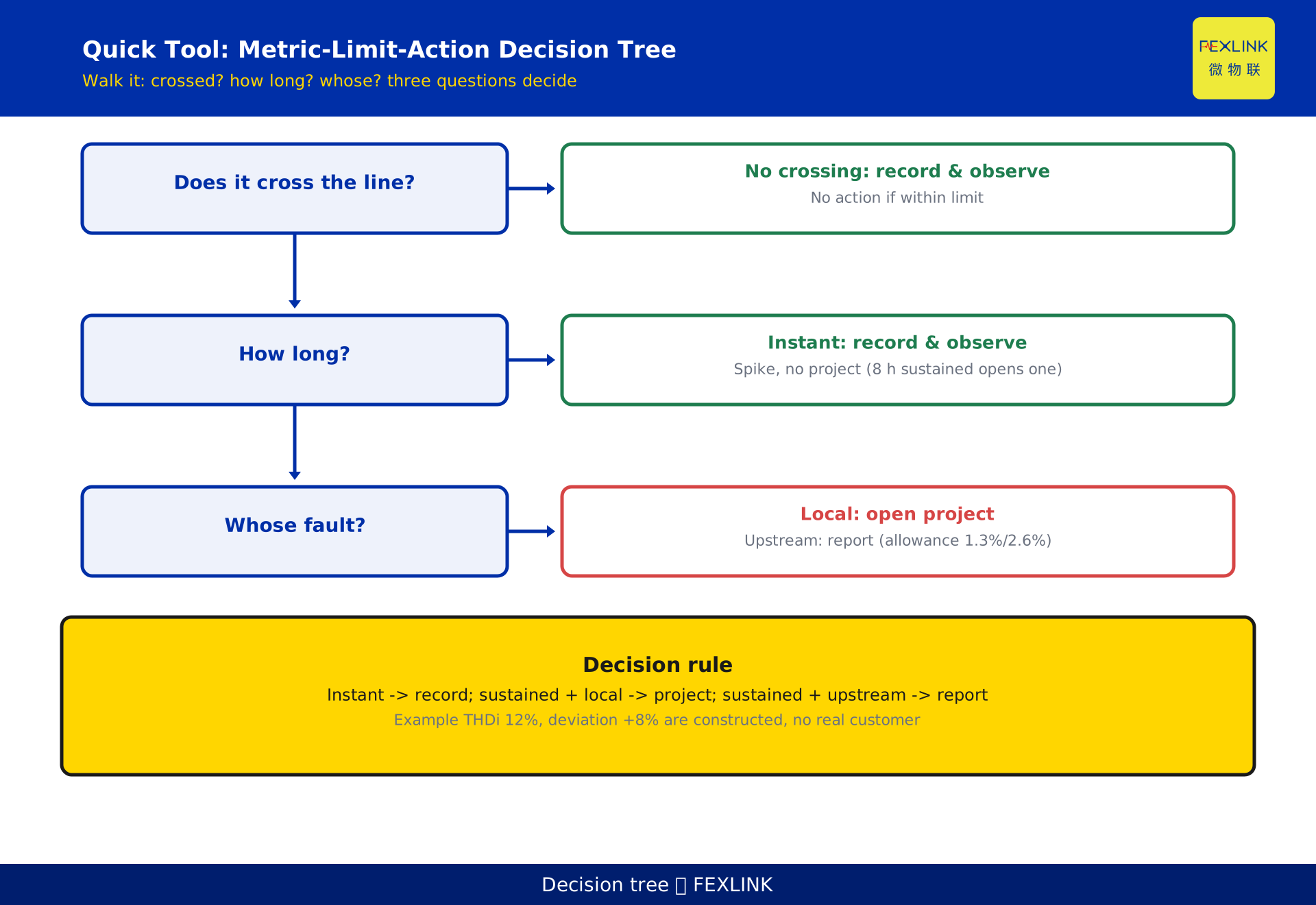
- Check the duration: is the crossing instantaneous or sustained? Instantaneous → record; sustained → open a project. This step answers "should we act now".
- Assign responsibility: caused by the local load or the upstream source? Local owns the remediation; upstream owns the escalation. This step answers "who should act".
The explicit decision rule: instantaneous excursion → record and observe; sustained excursion + local cause → open a remediation project; sustained excursion + upstream cause → report to the power dispatcher and negotiate. Without these three steps, more readings are just a pile of numbers.
8. How monitoring lands: turning judgment into routine
Judgment cannot rely on someone reading meters by hand every day. Continuous monitoring at the point of common coupling is the prerequisite.
At the point of common coupling or on major feeders, deploy the ESE power-quality monitor, which continuously acquires THDu, THDi, three-phase voltage unbalance and voltage deviation, and raises excursion alarms and statistics against GB/T 14549, GB/T 12325 and GB/T 15543, automatically separating "instantaneous vs sustained". Where local, circuit-level judgment with control action is needed, the SFE power-quality measurement and control unit pushes the logic down to the distribution circuit. Both fit the power-quality monitoring solution, forming a closed loop of monitor — alarm — locate — remediate.
One park used such a device to find that an ageing rectifier had long kept the coupling-point THDi around 12% (example value); taking it offline brought the excursion down, confirming local responsibility, after which a project replaced the rectifier and the excursion disappeared. This scenario is constructed to illustrate the monitoring logic and represents no real customer.
9. Common misjudgments and handling advice
Three pits are most easily fallen into on site.
Misjudgment 1: treating an instantaneous spike as sustained exceeding. A voltage dip from one equipment start-up gets called "voltage deviation exceeding every day". Handling: re-judge using a statistical window (such as the 95% probability large value), not the single-point maximum.
Misjudgment 2: looking only at THDi, ignoring THDu and skipping Table 2 conversion. Seeing THDi 12% on the meter and rushing to remediate, without converting the current allowable value by voltage class and reference short-circuit capacity. Handling: the current side must consult Table 2; the voltage side compares directly to Table 1.
Misjudgment 3: judging unbalance by neutral-current magnitude. A large neutral current does not equal negative-sequence unbalance above 2%; the two have different dimensions. Handling: read the negative-sequence voltage unbalance metric directly and compare it to GB/T 15543.
The general principle of handling: judge first, remediate later; no action if not crossing the line; once crossing, fix responsibility before fixing the plan.
10. Frequently asked questions (FAQ)
Q: The meter shows THDi 12% every day — must we remediate immediately?
Not necessarily. THDi is a current metric; it must be converted per GB/T 14549-1993 Table 2 into the individual harmonic currents injected into the point of common coupling and compared with the allowable values for that voltage class and reference short-circuit capacity. Then check whether it is instantaneous or sustained, and finally whether the local load caused it. Only when all three steps pass do you open a project; otherwise record and observe first.
Q: Is a voltage deviation of +8% definitely exceeding?
For 20 kV and below three-phase systems, ±7% is the red line, so +8% has crossed it. But for 220 V single-phase, the lower bound allows down to −10% and the upper to +7%, so +8% still exceeds; for 35 kV and above, the limit is the sum of absolute deviations ≤10%, so +8% alone may not exceed. The measurement point (transformer side or end) also affects the conclusion — confirm it first.
Q: Which is the standard, 2% or 4% for three-phase unbalance?
Both. The normal-operation limit at the point of common coupling is 2%, and 4% is allowed for short durations (typically the 1–3 minute order of magnitude). In addition, the unbalance caused by a single customer is tighter — generally 1.3%, 2.6% for short durations. When judging, first distinguish "whole coupling point" from "local injection".
Q: Why are the limits for voltage THDu and current THDi different?
THDu is a coupling-point voltage assessment; the standard gives fixed percentages by voltage class directly (Table 1). THDi is a user-injected current assessment; the allowable values vary with voltage class and reference short-circuit capacity (Table 2) and cannot be judged by a single fixed number away from the site. The two have different assessment objects and dimensions.
Q: When it exceeds, how do we quickly tell who owns it?
Monitor at the point of common coupling and take the main local non-linear loads offline one by one, watching whether the excursion disappears. If it disappears, the local load caused it and the local side owns the remediation; if not, the source is upstream or external, and you should report to the power dispatcher or negotiate rather than blindly adding local mitigation equipment.
Scope and limitations
- The three red lines come respectively from GB/T 12325-2008, GB/T 14549-1993 and GB/T 15543-2008, all current standards; specific limits are subject to the standard text and the official published version, and quantitative conclusions must be re-checked after any standard revision.
- Voltage-deviation limits differ by voltage class (10% at 35 kV and above, ±7% for 20 kV and below three-phase, +7% / −10% for 220 V single-phase); confirm the measurement point's voltage class and location before judging.
- Judging current harmonics THDi must follow GB/T 14549-1993 Table 2, converting by voltage class and reference short-circuit capacity; this article does not list all Table 2 values, and the specific allowable values are those in the original standard. Voltage harmonic THDu limits (Table 1) can be compared directly.
- The 2% / 4% unbalance refers to the negative-sequence voltage unbalance at the point of common coupling; the single-customer allowance (generally 1.3%, 2.6% short-term) is tighter, and the assessment object must be distinguished when judging.
- The THDi 12% and voltage deviation +8% figures and the park scenario in this article are constructed to illustrate the reading logic and represent no real customer, project or measurement data.
- The ESE power-quality monitor, SFE power-quality measurement and control unit and power-quality monitoring solution mentioned here are subject to the latest selection manual and product knowledge base; this article does not constitute a selection or procurement recommendation.
Frequently Asked Questions
THDi 12% and Voltage Deviation +8% on the Meter
Most percentages the meter prints every day are normal fluctuations; only those that touch a national-standard limit count as "exceeding"