 FEXLINK Research Institute
The short answer
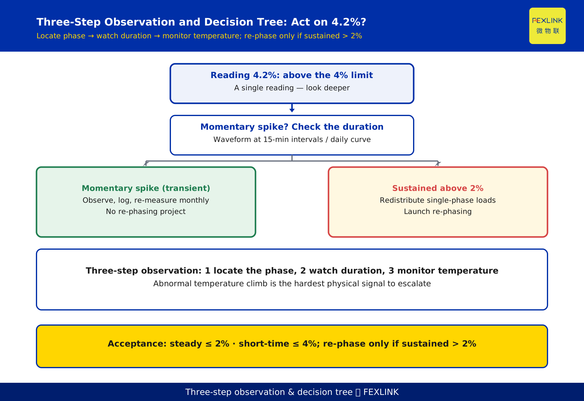
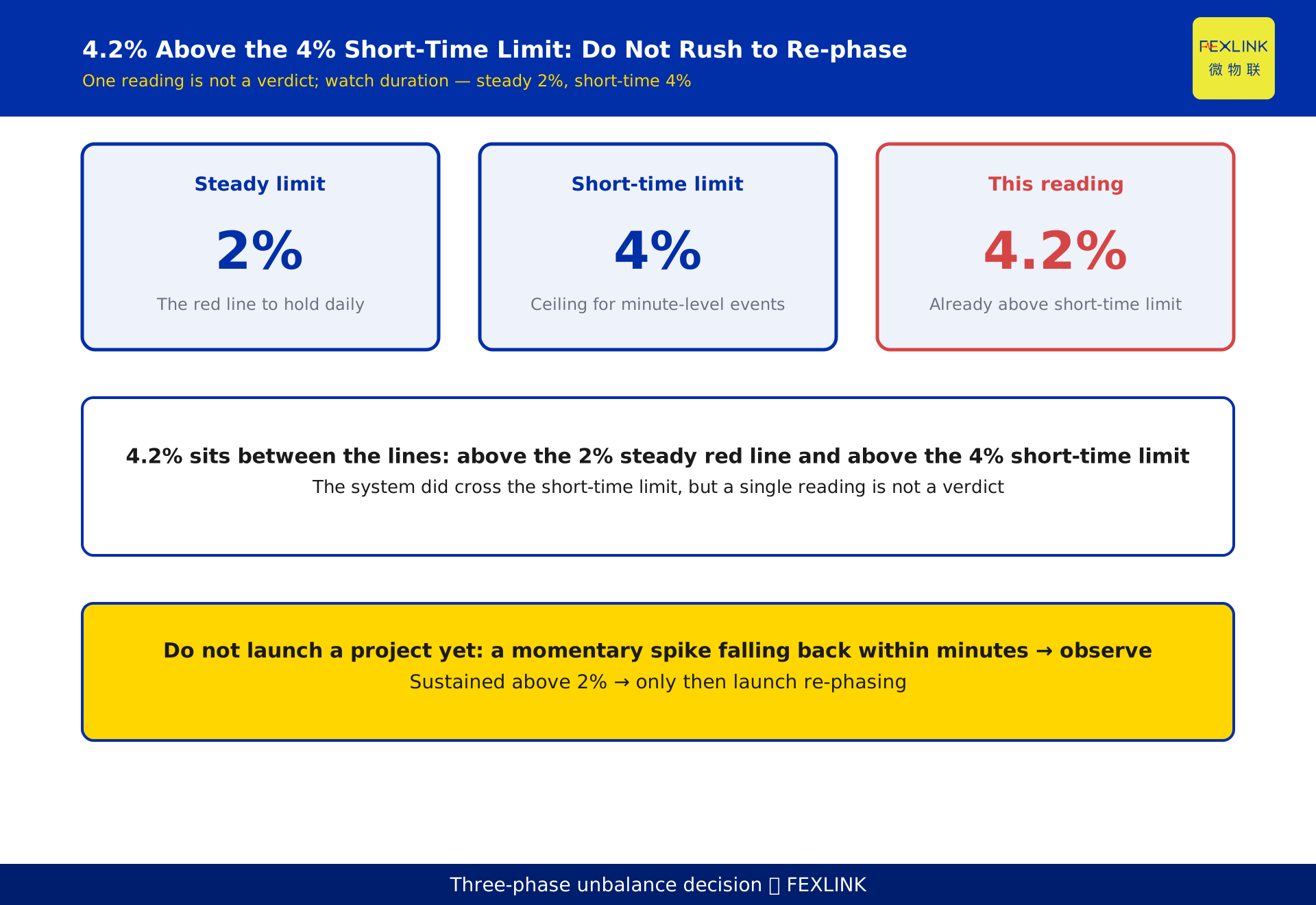
Per GB/T 15543, the negative-sequence voltage unbalance at a public connection point is allowed up to 2% in normal operation, and must not exceed 4% for short durations. The 4.2% you measured is already above the 4% short-time limit, but whether you should act right away depends on duration, not on a single reading. A momentary spike (a motor start, a single-phase surge) that falls back within minutes does not call for phase balancing; only a sustained level above 2% justifies a re-phasing project. After any over-limit reading, do three things first: locate the phase carrying the concentrated single-phase load, observe how long the over-limit lasts, and monitor the transformer temperature rise.
1. Two lines to remember: 2% is the steady red line, 4% is the short-time limit
Three-phase unbalance is a question of "whether it exceeds the limit," not "whether it exists." GB/T 15543 draws two lines of different nature:
- Normal limit 2%: this is the red line to hold daily; the negative-sequence voltage unbalance should stay below it most of the time.
- Short-time limit 4%: this is the ceiling allowed for minute-level, non-sustained conditions—such as a large motor starting, a spot welder firing, or a single-phase load switching on. It does not mean "you may sit at 4% indefinitely"; it only tolerates a brief excursion.
A common mistake is to treat 4% as the "pass line," relaxing until the reading touches 4% and panicking only then. The correct reading is the opposite: 2% is the line to defend long term; 4% is merely an emergency buffer. The 4.2% in this article sits above both lines—it shows the short-time limit was crossed, but one reading alone cannot decide whether action is needed.
2. What the number 4.2% actually means
Between the two lines, the conclusion is clear: 4.2% exceeds the 4% short-time limit, so the system is genuinely over-limit at that moment; but it does not say whether this was a one-off spike or a sustained high level.
The two cases demand completely different responses:
- If it was a momentary spike: imagine a 1000 kVA workshop whose welder fires dozens of times a day, each time pushing one phase to 120 A while the other two sit at 95 A and 93 A, spiking the unbalance to 4.2%, then falling back to 1.6% after 8 minutes. For this profile the fix priority is low—shutting down to tame transient surges costs more than it saves.
- If it is sustained: one phase permanently carries a single-phase line, currents differ by over 20% year-round, and unbalance hovers between 3% and 4%. That is the real re-phasing candidate.
So 4.2% is not a verdict; it is a prompt saying "look deeper." The only criterion is duration.
3. How unbalance is calculated (and how this differs from KD-0461)
The voltage unbalance is defined as the ratio of the negative-sequence component to the positive-sequence component: ε_U = U₂ / U₁ × 100%, where U₁ is the positive-sequence voltage and U₂ the negative-sequence voltage. Current unbalance is computed the same way, swapping current for voltage.
Here we draw a boundary with the neighboring article KD-0461 (article 461): KD-0461 explains "how to calculate"—symmetrical components and how the meter samples. This article explains "what to do after the number comes out." The two are upstream and downstream, so this article does not re-derive it; it takes an enlarged negative-sequence component as a given and focuses on the three actions after the reading.
One intuition: unbalance is essentially the share of the negative-sequence component. The larger it is, the more asymmetric the phases, and the closer to "one phase carrying most of the load."
4. Do not rush to re-phase after an over-limit: the three-step observation
When a reading exceeds the limit, the first reaction should not be to shut down and re-phase now. Complete three observations first; these steps are the backbone of this article and its biggest increment over KD-0461.
Step 1: locate the phase with the concentrated single-phase load. Pull the three-phase currents and see which phase is clearly larger. Unbalance is almost always a disproportionate single-phase load on one phase—a furnace, a charger, or a lighting circuit wired to one phase. A device like the ESB three-phase unbalance monitor continuously tracks three-phase current and voltage unbalance and directly flags the phase with the larger current, turning "which phase is wrong" from a guess into a data conclusion.
Step 2: observe the duration. Using waveform records or daily curves at intervals no coarser than 15 minutes, see whether 4.2% "flashed by" or "refuses to leave." A momentary spike and a sustained high level need different remedies.
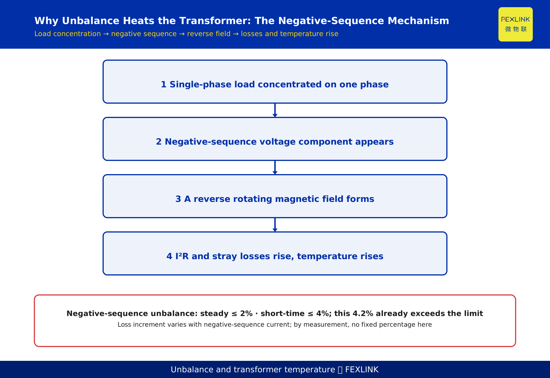
Step 3: monitor the transformer temperature rise. Unbalance creates a reverse rotating magnetic field inside the transformer, raising losses and temperature. Whether the winding or oil temperature climbs abnormally is the hardest signal for "should we act now"—if the temperature is steady, the over-limit has not yet harmed the equipment; if it keeps rising, raise the priority.
5. Why unbalance makes the transformer "run hot"
This step explains the mechanism, to help you understand why "watch the temperature" is a valid criterion.
Under ideal balance, currents are symmetric, the negative-sequence component is near zero, and one forward field carries the load. Once unbalance appears, a negative-sequence component enters and excites a reverse rotating magnetic field in motors and transformers. This reverse field has two consequences:
- It induces a double-frequency current in the rotor or windings, raising both I²R losses and stray losses;
- The rising losses convert directly into heat, lifting the winding and oil temperatures and accelerating insulation aging.
A key caveat: the loss increment varies with the magnitude of the negative-sequence current and has no fixed percentage. You cannot quote "unbalance of 4% raises losses by so much"—the figure depends on transformer capacity, load factor, and the negative-sequence current, and must come from measurement or manufacturer data. That is also why watching the temperature beats memorizing a loss formula: temperature is the visible result.
6. Redistributing single-phase loads across three phases (how re-phasing works)
Only when the three-step observation confirms a "sustained high-level real problem" do you enter the re-phasing stage. Re-phasing in one sentence: take the single-phase loads concentrated on one phase and spread them across the three phases so the currents become as close as possible.
In practice:
- Inventory: register every single-phase load in the workshop (furnaces, chargers, lighting, air conditioning) by the phase it is connected to, and find the "heavy phase."
- Re-balance: move some single-phase loads from the heavy phase to the light phases, or assign grouped single-phase loads in A/B/C rotation (for example, three-phase lighting distribution with phase rotation).
- Re-measure: at the same metering point and with the same meter, re-measure the unbalance and confirm the steady level returns below 2% and the short-time stays within 4%.
A device like the SFB three-phase balancing controller acts after re-phasing to provide balancing control and continuous monitoring, turning "balance once" into "hold the balance continuously." Selection and electrical parameters should follow the latest selection manual; this article gives no specific model specifications.
7. A worked example: should a 4.2% workshop launch a project?
The following scenario is constructed to illustrate the decision logic and represents no real customer or project.
A machining workshop in an industrial park is served by a 1000 kVA transformer. During an inspection, phase A current reads 120 A, phase B 95 A, phase C 93 A, and the monitor reports an unbalance of 4.2%, already above the 4% short-time limit. The operator wonders: should we shut down and re-phase immediately?
Following the three-step observation: Step 1, locate—phase A is 27 A larger, and wiring shows a single-phase furnace feeder on phase A only. Step 2, duration—the daily curve shows the furnace welds about 8 minutes per day, then currents return to 110 A / 108 A / 107 A and unbalance falls back to 1.6%. Step 3, temperature—the winding temperature stays stable with no abnormal climb.
Conclusion: this 4.2% is a momentary spike from furnace welding, not a sustained high level, so no re-phasing project is launched. The action instead is: record the condition, add the furnace surge to the monthly re-measurement checklist, and keep monitoring the transformer temperature. If the future daily curve shows a sustained level above 2%, then start re-phasing.
8. How to accept the work after remediation: re-measurement standard
After re-phasing or adding balancing control, acceptance checks one thing: re-measure the unbalance at the same metering point with the same meter. The pass criteria match the standard:
- Steady ≤ 2%: remediation meets the target, close the loop;
- Short-time ≤ 4%: the permitted surge condition remains compliant;
- If the steady re-measurement is still above 2%, the load re-balancing was not done properly and you must return to step six and re-inventory.
Acceptance is not "pass once." Keep continuous waveform records to confirm the system is persistently flat, not just flat when tested. The always-on ESB monitor retains the before-and-after curves, making acceptance evidence-based.
9. How products help you close the loop
Stringing "reading—observation—decision—remediation—acceptance" together relies on edge data and automatic criteria, not on manual monthly meter reading.
- ESB three-phase unbalance monitor (full name on first appearance): continuously monitors three-phase current and voltage unbalance, automatically locates the phase with the larger current, and flags over-limit against the 2%/4% dual lines of GB/T 15543. It answers which phase is wrong and whether it is over limit.
- SFB three-phase balancing controller (full name on first appearance): after re-phasing or load adjustment, it provides three-phase balancing control and continuous monitoring, turning one-time re-phasing into a long-term hold. It follows the latest selection manual; this article gives no electrical specifications.
Together they map to the related solution "digital electrical intelligent supervision system": monitor to produce data, control to level the phases, re-measure to close the loop—all logged.
10. FAQ
Q: The monitor reports 4.2%; should I shut down and re-phase right away?
Not necessarily. 4.2% only crosses the 4% short-time limit; the key is duration. A momentary spike (falling back within minutes after equipment start) does not call for urgent action; only a sustained level above 2% justifies a re-phasing project.
Q: Which is the pass line, 2% or 4%?
2% is the normal allowable value and the red line to defend daily; 4% is the short-time limit used only for minute-level, non-sustained conditions, and does not mean you may sit at 4% long term. The correct goal is to keep the steady level stable below 2%.
Q: Does unbalance increase the electricity bill?
Unbalance itself is not billed directly, but it raises transformer and motor losses and temperature, and over time increases reactive and additional losses while accelerating insulation aging. The specific loss increment varies with the negative-sequence current and must come from measurement or manufacturer data; this article gives no fixed percentage.
Q: Is re-phasing just disconnecting the load from one phase?
No. It means redistributing the single-phase loads concentrated on one phase evenly across the three phases so the currents become as close as possible. Blindly cutting load can create a new imbalance or a supply gap; you should inventory by phase first, then re-balance.
Q: How do I confirm the remediation actually worked?
Re-measure at the same metering point with the same meter: steady ≤ 2% and short-time ≤ 4% means it passes. Keep continuous waveform records to confirm it is persistently flat, not just flat at the instant of testing.
Scope and limitations
- The three-phase unbalance limits discussed here (steady 2%, short-time 4%) are based on GB/T 15543-2008 "Power quality—Three-phase voltage unbalance" (currently effective, replacing the 1995 edition). This article cites only the standard name and the two limits, not clause numbers; specific clauses should follow the current standard text.
- "Short-time" means minute-level, non-sustained conditions (such as equipment start surges), not a fixed duration; whether an over-limit counts as sustained should be judged from waveform records and daily curves.
- The additional losses and temperature rise caused by unbalance are qualitative: the negative-sequence component excites a reverse rotating magnetic field, raising I²R losses and stray losses and increasing temperature; the loss increment varies with the negative-sequence current, and specific values must come from measurement or manufacturer data—this article gives no fixed percentage.
- The workshop example in section 7 (1000 kVA transformer, phase A 120 A / phase B 95 A / phase C 93 A, 4.2%, 8 minutes, falling back to 1.6%) is constructed to illustrate the decision logic and represents no real customer, park, or project.
- The functional roles of the ESB three-phase unbalance monitor and the SFB three-phase balancing controller described here are general; specific models, electrical specifications, and selection should follow the latest product selection manual, and this article is not a procurement recommendation.
- Distinction from KD-0461 (unbalance calculation principles): this article covers "the decision after a number is measured," while KD-0461 covers "how to calculate"; the increment here is the three-step action after the 2%/4% grading (locate the concentrated phase, observe duration, monitor temperature rise, then launch re-phasing).
Frequently Asked Questions
Three-Phase Unbalance Reads 4.2%
Per GB/T 15543, the negative-sequence voltage unbalance at a public connection point is allowed up to 2% in normal operation