 FEXLINK Research Institute
The short answer
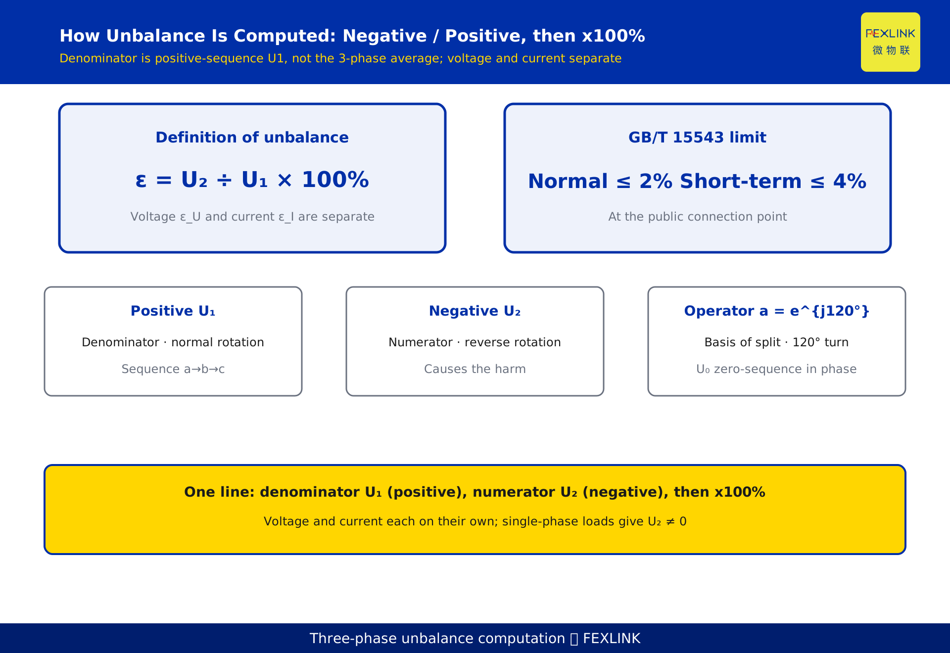
When the panel reports a three-phase unbalance trip, that percentage is not computed by comparing the three ammeter readings. It comes from the method of symmetrical components: decompose the three-phase voltage (or current) into a positive, a negative and a zero sequence, then take the negative-sequence component divided by the positive-sequence component, times 100%: ε_U = U₂ / U₁ × 100% (for current, ε_I = I₂ / I₁ × 100%). GB/T 15543 sets the normal voltage unbalance at the public connection point to no more than 2%, and no more than 4% for short durations. The precise answer to "which phases, and what do we divide by" is: voltage and current are computed separately; the denominator is U₁, not the three-phase average; the numerator is U₂. Single-phase loads piling up on one phase are exactly what makes the negative sequence U₂ ≠ 0.
1. The bottom line: what do you divide by
Many field engineers, seeing phase currents of 320 A, 300 A and 280 A, compute (320 − 280) / 300 and call that the unbalance. It tells you "how far off," but it is not the national-standard definition.
The GB/T 15543 definition is based on symmetrical components. The denominator is the positive-sequence component U₁, the numerator is the negative-sequence component U₂ — not the three-phase average, and not the difference between the largest and smallest phase. Voltage unbalance and current unbalance are computed separately and must not be mixed. Lock this down first; everything else follows.
2. Symmetrical components: how one unbalanced set splits into three
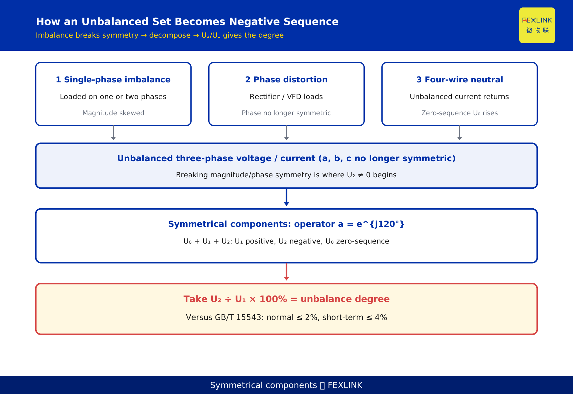
Any unbalanced set of a, b, c phasors can be uniquely decomposed into three balanced sequences. Define the operator a = e^{j120°} (rotate the phasor 120° counter-clockwise), and a² = e^{j240°}. Then:
- Positive sequence: three equal magnitudes, phases 120° apart, sequence a→b→c, the same direction as normal system rotation.
- Negative sequence: three equal magnitudes, also 120° apart, but sequence a→c→b, the reverse direction.
- Zero sequence: three equal magnitudes, all in phase.
The forward transform:
U_a = U₀ + U₁ + U₂ U_b = U₀ + a²U₁ + aU₂ U_c = U₀ + aU₁ + a²U₂
The inverse transform (from measured three-phase values to the three sequences):
U₀ = (U_a + U_b + U_c) / 3 U₁ = (U_a + aU_b + a²U_c) / 3 U₂ = (U_a + a²U_b + aU_c) / 3
Current sequences I₀, I₁, I₂ are exactly the same construction. The positive sequence is the "normal" component we want to keep; the negative sequence is the "reverse" component that breaks symmetry; the zero sequence is normally zero in a three-wire balanced system and appears, lifting the neutral current, in an unbalanced four-wire system.
3. The definition and the GB/T 15543 algorithm
Voltage unbalance:
ε_U = (U₂ / U₁) × 100%
Current unbalance:
ε_I = (I₂ / I₁) × 100%
Here U₁, U₂ (or I₁, I₂) are the magnitudes of the positive- and negative-sequence components from the previous section. The key is denominator U₁, numerator U₂ — that is the precise answer to "which phases, what do we divide by." Voltage and current are computed separately; neither is the denominator of the other.
GB/T 15543 (current edition 2008, replacing the 1995 edition), "Power quality — Three-phase voltage unbalance," sets the normal voltage unbalance at the public connection point to 2%, and no more than 4% for short durations. These are the typical limits given by GB/T 15543-2008; the current edition of the standard governs. Note this standard governs voltage unbalance; current unbalance has no identically named mandatory limit, yet it is an early warning of voltage unbalance and many equipment problems, so it should be tracked on site too.
4. A worked example: where the negative sequence comes from
Take a set of per-unit voltages: U_a = 1.0∠0°, U_b = 0.9∠−120°, U_c = 1.1∠120° — only slightly unbalanced in magnitude, phase still positive sequence. Plug into the inverse transform:
U₁ = (1.0 + 0.9 + 1.1) / 3 = 1.0 U₂ = −j0.058, |U₂| ≈ 0.058 U₀ = j0.058, |U₀| ≈ 0.058
So the voltage unbalance is ε_U = 0.058 / 1.0 × 100% ≈ 5.8%.
A few things to notice: first, with phase magnitudes differing by only ±10%, the negative sequence already reaches about 5.8%, which shows how sensitive U₂ is to asymmetry; second, U₂ and U₀ are of the same order here because only magnitude, not phase, was disturbed; third, 5.8% already exceeds the 4% short-term limit of GB/T 15543 and is a level that needs action. This example is constructed to illustrate the algorithm and does not represent any real customer or project.
5. The field short-cut and how far it drifts
On site there is often no time for a full symmetrical-component decomposition, so a short-cut is used:
ε ≈ (largest phase magnitude − three-phase average magnitude) / three-phase average magnitude × 100%
A second variant is (max − min) / avg × 100%. The two are not equivalent: the second doubles the deviation, so on the same data it reads twice the first. Check against the Section 4 data: the exact ε_U is 5.8%, (max − avg)/avg gives 10%, and (max − min)/avg gives 20% — an overestimate of up to 3.5×. So a short-cut is a screen only; it must not be compared with the 2% / 4% limits. In one line: the quick estimate is for the first-pass "is there a problem" screen; formal assessment, accountability and reports must use U₂/U₁ from symmetrical components. Any comparison against a limit must use the exact value.
6. Why single-phase loads create negative sequence
The physical source of U₂ ≠ 0 is that the three-phase magnitudes or phases are no longer symmetric. A single-phase load — a single-phase motor, single-phase heating, an EV charger, single-phase lighting — hangs on only one or two phases, artificially "loading" one phase and "lightening" another, breaking magnitude symmetry; a single-phase rectifier or variable-frequency load also introduces phase distortion, further breaking phase symmetry.
In a four-wire system, single-phase loads piling up also send unbalanced current back through the neutral. The neutral current can reach a high fraction of the phase current, and the neutral usually has no overcurrent protection, so sustained overcurrent is a thermal risk. Spreading single-phase loads as evenly as possible across the three phases, and controlling the total single-phase load on any one phase, is the fundamental way to reduce negative sequence and unbalance.
7. The impact chain: from one heavy phase to overheating
Cause → mechanism → consequence, the chain is clear:
Single-phase loads pile up → three-phase current / voltage becomes asymmetric → negative-sequence component U₂ ≠ 0 → inside rotating machines (generators, motors) it induces a reverse rotating field at twice the line frequency → extra heating, reduced output, lower efficiency; the transformer suffers added loss and local overheating from negative sequence and must run de-rated; negative sequence can also raise the risk of protective-relay mis-operation and increase neutral overcurrent.
In other words, unbalance is not just "ugly numbers on a meter": it creates a reverse field and added loss inside the equipment, shortening life and wasting energy over time. Treating negative sequence essentially means bringing the three phases back to symmetry and driving the reverse component toward zero.
8. How to use it on site: measure, decompose, compare, close the loop
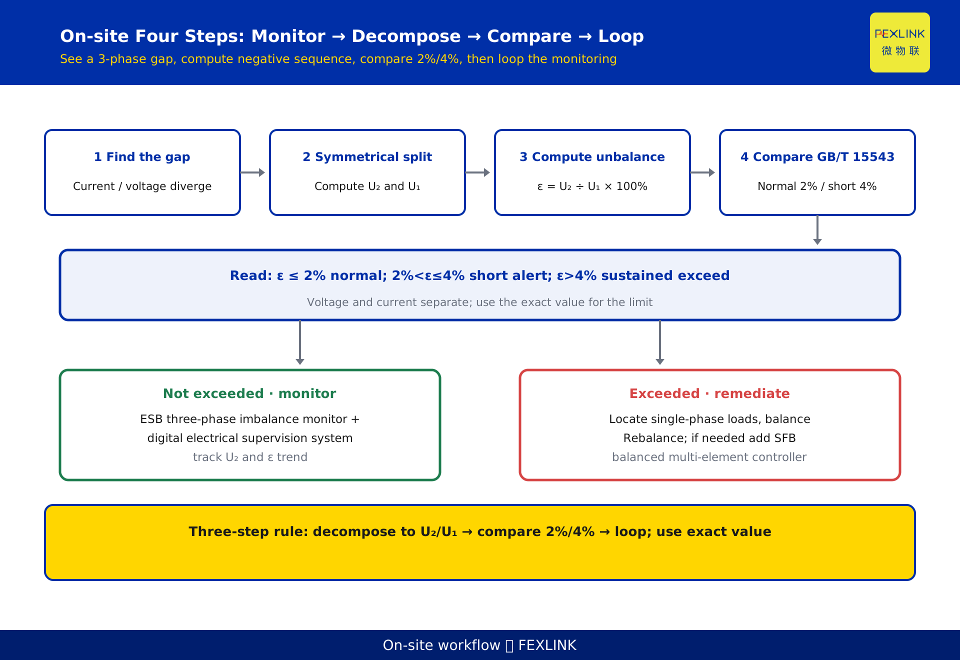
On site, four steps:
- Monitor: continuously acquire three-phase voltage and current on the distribution circuit, not just an instantaneous ammeter glance.
- Decompose: apply symmetrical components to each sampling window to get U₂, U₁ (and I₂, I₁).
- Compare: use ε = U₂/U₁ × 100% against the GB/T 15543 2% / 4% limits to decide normal, short-term exceedance, or sustained exceedance.
- Close the loop: on exceedance, locate the single-phase load and rebalance the phases; then keep tracking the trend instead of measuring once and forgetting.
To keep tracking negative-sequence and unbalance trends on site, the ESB three-phase imbalance monitor works with the digital electrical supervision system: the monitor measures the three-phase voltage and current and computes negative-sequence and unbalance locally, and the upper system aggregates multiple circuits for trend, alarm and work order. The SFB balanced three-phase multi-element controller also covers unbalance monitoring on top of measurement and control, suiting sites that need temperature, energy and other elements collected together.
9. Where the products fit
The two devices above have distinct roles. The ESB three-phase imbalance monitor is for the single subject of "imbalance": it measures three-phase voltage and current and computes negative/positive-sequence components and unbalance locally, suiting circuits already suspected or already exceeding, where a trend must be watched. The SFB balanced three-phase multi-element controller is a "measurement + unbalance monitoring" combination that yields unbalance alongside energy, suiting new builds or retrofits where several monitoring functions are laid down at once.
Above both, the digital electrical supervision system ties them together: it pulls ESB and SFB data from scattered circuits, does cross-circuit comparison, long-term trend and exception work orders, turning "one-off measurement" into "continuous operation." Specific models and parameters follow the latest selection manual; this article is not a selection or procurement recommendation.
FAQ
Q: The three-phase currents are 320, 300 and 280 A. What is the unbalance?
By the national-standard method you must first run the symmetrical-component decomposition to get U₂/U₁ (or I₂/I₁ for current); you cannot take (320 − 280) / 300 as the unbalance directly. That number only shows "max-min deviation as a share of the average" and works as a screen, but it is not the GB/T 15543 definition.
Q: Why is the denominator the positive sequence U₁, not the three-phase average?
Because unbalance measures "how far from the normal symmetric state," and the positive sequence is exactly that normal reference. Using the three-phase average dilutes the effect of negative sequence and diverges clearly under severe unbalance. The standard uses U₂/U₁.
Q: Is there a limit for current unbalance?
GB/T 15543 governs voltage unbalance (2% normal, 4% short-term). Current unbalance has no identically named mandatory limit, but it is an early warning of voltage unbalance and equipment problems, so it should be tracked on site — especially neutral current in four-wire systems.
Q: Can the field (max−min)/avg estimate be used?
Yes, for the first-pass "is there a problem" screen. But it runs systematically high: on the Section 4 data the exact value is 5.8%, (max−avg)/avg gives 10% and (max−min)/avg gives 20%. Conversely, when phase shift dominates, both short-cuts approach zero and can miss an exceedance. So it can screen but not judge; formal assessment, limit comparison and reports must use the exact symmetrical-component value.
Q: How to choose between ESB and SFB?
If you only watch imbalance and need a continuous trend, choose the ESB three-phase imbalance monitor; if a new build or retrofit must also collect temperature, energy and other elements, choose the SFB balanced three-phase multi-element controller. Specific models follow the latest selection manual.
Scope and limitations
- The symmetrical-component method, the unbalance definition and the GB/T 15543 limits discussed here apply to three-phase voltage and current unbalance analysis in low- and medium-voltage distribution; the sequence-component principle is the same at higher voltages, but limits and management requirements follow the standard for the relevant voltage level.
- The 2% and 4% cited from GB/T 15543-2008 are typical limits; the current edition of the standard governs, and quantitative conclusions must be re-checked after a revision.
- The worked example in section 4 (U_a = 1.0∠0°, U_b = 0.9∠−120°, U_c = 1.1∠120°, ε_U ≈ 5.8%) is constructed to illustrate the algorithm and does not represent any real customer or project.
- The gap between the field short-cuts and the exact U₂/U₁ varies with the degree of unbalance and with phase shift; the 5.8%, 10% and 20% figures all come from the single constructed dataset in Section 4 and only show the direction of the overestimate, not a general conversion factor. Any limit comparison must use the exact value.
- Specific models and parameters of the ESB three-phase imbalance monitor, the SFB balanced three-phase multi-element controller and the digital electrical supervision system follow the latest selection manual and product knowledge base; this article is not a selection or procurement recommendation.
Frequently Asked Questions
The three-phase currents are 320, 300 and 280 A. What is the unbalance?
By the national-standard method you must first run the symmetrical-component decomposition to get U₂/U₁ (or I₂/I₁ for current); you cannot take (320 − 280) / 300 as the unbalance directly. That number only shows "max-min deviation as a share of the average" and works as a screen, but it is not the GB/T 15543 definition.
Why is the denominator the positive sequence U₁, not the three-phase average?
Because unbalance measures "how far from the normal symmetric state," and the positive sequence is exactly that normal reference. Using the three-phase average dilutes the effect of negative sequence and diverges clearly under severe unbalance. The standard uses U₂/U₁.
Is there a limit for current unbalance?
GB/T 15543 governs voltage unbalance (2% normal, 4% short-term). Current unbalance has no identically named mandatory limit, but it is an early warning of voltage unbalance and equipment problems, so it should be tracked on site — especially neutral current in four-wire systems.
Can the field (max−min)/avg estimate be used?
Yes, for the first-pass "is there a problem" screen. But it runs systematically high: on the Section 4 data the exact value is 5.8%, (max−avg)/avg gives 10% and (max−min)/avg gives 20%. Conversely, when phase shift dominates, both short-cuts approach zero and can miss an exceedance. So it can screen but not judge; formal assessment, limit comparison and reports must use the exact symmetrical-component value.
How to choose between ESB and SFB?
If you only watch imbalance and need a continuous trend, choose the ESB three-phase imbalance monitor; if a new build or retrofit must also collect temperature, energy and other elements, choose the SFB balanced three-phase multi-element controller. Specific models follow the latest selection manual.