 FEXLINK Research Institute
The short answer
Yes, and it does not require two separate platforms. For tenant-level water and electricity sub-metering, the leanest path is: electricity meters with RS485/Modbus hang directly on a bus; pulse-output water meters are read through dry-contact digital modules; both signal types converge on one edge gateway that normalizes the protocols and pushes everything to one cloud platform, where sub-metering and billing happen in a single system. The whole conclusion fits one sentence — merge "electricity on one system, water on another" into "two heterogeneous signals sharing one network, one gateway, one platform." We first put the savings in a side-by-side, then the mechanism, the wiring, the configuration and the phasing.
1. The real cost of running two separate systems
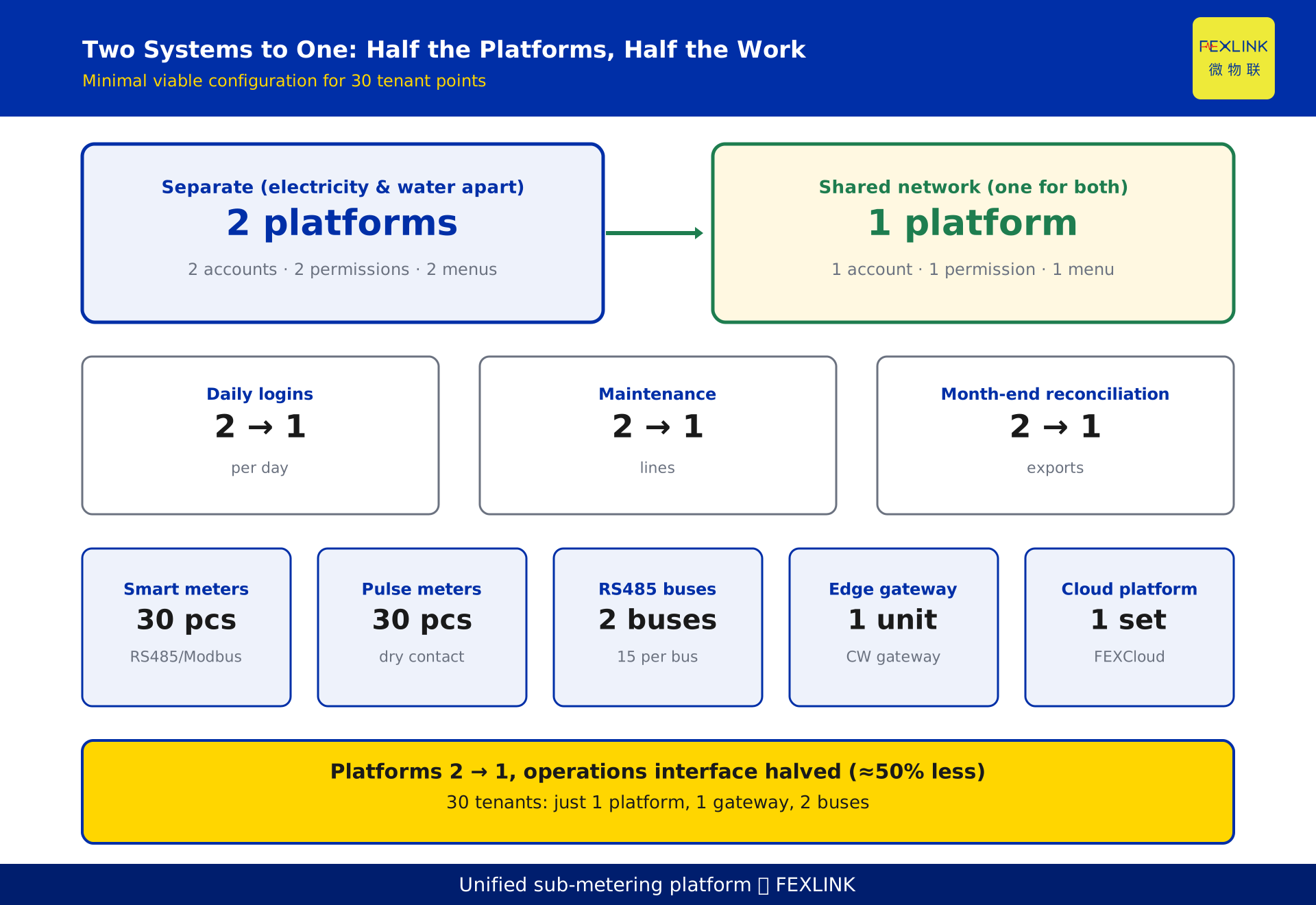
Property managers hesitate to sub-meter water and electricity less for technical difficulty and more because the math does not add up. Separate systems mean three duplicated jobs. First, two platforms — electricity in one metering and billing system, water in another, so operators log in twice daily. Second, two maintenance tracks: firmware, gateway drop-offs and meter faults handled on two lines. Third, two reconciliations: month-end charges exported from two systems and merged by hand, exactly where errors and tenant disputes creep in. These are not one-off capital but ongoing monthly operations; turning "two" into "one" saves recurring reconciliation labour and troubleshooting, not a one-time purchase.
2. The core idea of the minimal scheme: heterogeneous signals on one network
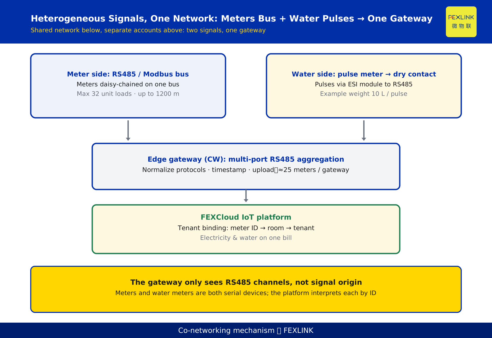
The electricity and water signals look nothing alike: the meter outputs numeric quantities — voltage, current, power, energy; the water meter outputs a stream of pulses. Yet both become a digital value on RS485. Most meters carry an RS485 interface and speak Modbus RTU, so quantities are read straight off the bus. A water meter has no RS485, but a pulse-output remote meter has a dry contact that closes once per fixed volume; wire it into a digital status monitor, and the module counts pulses and reports the tally over RS485. So the meter brings its own RS485, and the water meter becomes RS485 through the module — both signals collapse, at the physical layer, onto the same bus and interface.
This is precisely what makes co-networking possible: the two are not required to share a protocol, only to land on the RS485 channel the gateway receives. The gateway normalizes different sources, timestamps them and pushes them up; the platform binds "whose meter, which tenant."
3. How the two signals converge on one gateway
Figure 2 draws the path as a confluence: the electricity meter bus (RS485/Modbus) on the left, the water-meter pulses through dry-contact modules (also RS485) on the right, both meeting at one edge gateway. It normalizes protocols and pushes to FEXCloud, which binds each meter address to a room so one account shows both an electricity and a water line.
The point is that the gateway only recognises RS485 channels and does not care about the source. To it, both are "devices on a serial port" — only the reading's meaning differs. This "shared network below, separate accounts above" structure is the physical basis for compressing two systems into one.
4. Wiring the meters: smart meters straight on the RS485 bus
The easiest meter-side wiring is bus style. Smart meters with RS485/Modbus (for example the ESA/ZSA smart meter family, which carries an RS485/Modbus interface and hangs directly on the bus to collect per-circuit electrical quantities) are daisy-chained on one RS485 bus, polled by the gateway as master.
Two real engineering numbers apply. First, the RS485 standard limits one bus to 32 unit loads, so the meter count per bus is normally kept under 32. Second, at lower baud rates the RS485 maximum transmission distance is about 1200 m; beyond that the signal degrades and a repeater or split is needed. A common zoning rule: about 25 meters per gateway per zone; exceed it and open a second zone with a second gateway. This empirical figure (about 25 meters per gateway) comes from field zonal aggregation — it respects the per-bus load limit while leaving room for wiring and troubleshooting.
5. Wiring the water meters: pulse meters through dry-contact modules
The water side does not require replacing meters with smart ones; you only need remote meters with pulse output. A pulse-output remote meter has a dry contact (typically a reed switch or open-collector) that closes once per fixed volume — a constructed example uses 10 L per pulse, shown only to illustrate the wiring and not representing any real product — presenting a pair of passive contacts.
Wire the two dry-contact wires to an ESI digital status monitor (a dry-contact acquisition module that turns the pulse signal into a countable digital value), then aggregate many meters onto one RS485 feed through a module such as the CX-08R06AI08-C1 digital-input module (used to gather several meters' dry-contact pulses and report them to the gateway over RS485). The module supplies the voltage and counts pulses internally; the gateway reads each meter's cumulative value by address, and the platform computes consumption as "current minus previous."
The dry contact's advantage is simplicity and noise immunity: no voltage, no polarity, longest run on ordinary twisted pair to the same RS485 segment as the meters; it does not care whether the meter is mechanical or electronic — as long as it emits pulses, it connects.
6. Tenant binding: how meter IDs map to room numbers on the platform
Co-networking solves "how the signals come up," but what cuts reconciliation is "whose water and electricity is charged to whom" — done on the platform and called tenant binding. Each meter has a unique ID (communication address) in the gateway. The platform maps meter ID → room number → tenant contract, a three-column table. Metering pulls by meter ID; billing aggregates by room and tenant, so electricity and water sit side by side on one bill.
Meter replacement is the common headache: a swap gives a new ID, so the platform must update the binding table too, not just the hardware, or readings land on the wrong tenant. Archive the binding table with the meter register, update on every swap and log it — ideally maintained centrally on the platform, not in an operator's notebook.
7. Minimal viable configuration (with one checkable example)
The following constructed example puts the scheme into concrete quantities (constructed only to show the logic and not representing any real customer or project): one building in a park, 30 tenants, 30 sub-metering points.
Minimal configuration: 30 smart meters with RS485/Modbus across 2 RS485 buses (15 per bus, under the 32-unit limit); 30 pulse-output remote water meters feeding several RS485 branches through dry-contact modules; 1 CW gateway (an edge gateway aggregating electricity and water digital quantities over multiple RS485 ports and uploading uniformly) taking all buses; and 1 FEXCloud IoT platform for binding, metering and billing.
Totalled: 30 meters, 30 water meters, 2 buses, 1 gateway, 1 platform. Versus the separate scheme, the platform count drops from 2 to 1 and the operations interface halves. Figure 1 puts the key numbers side by side.
8. Phasing the rollout: which tenants first
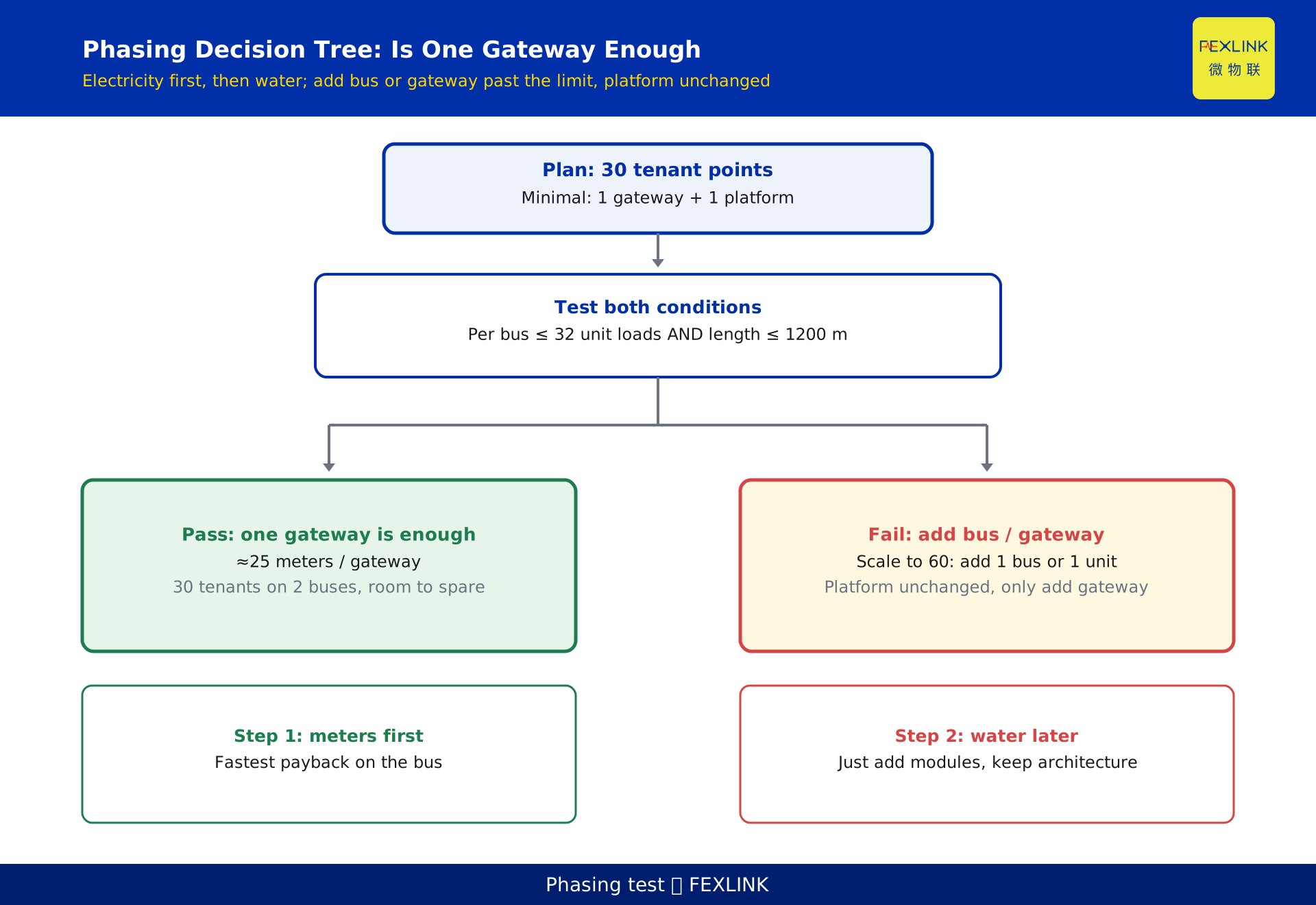
The other half of the value is phasing: the property need not wire the whole building at once, proceeding in batches paced by cash flow and occupancy. Recommended path — "electricity first, water second; dense zones first, sparse later." Do electricity first — meters hang straight on the bus, connect fastest, pay back most visibly (monthly electricity immediately attributable per tenant); then water, which only drops modules onto the existing bus without touching the architecture. Prioritise high-occupancy floors and disputed-common-area units; defer cold zones.
The hard test for "is one gateway enough": no more than 32 unit loads per bus and no bus longer than 1200 m. With 30 tenants split across 2 buses at 15 each, wide headroom remains; grows to 60, add a bus or gateway — platform unchanged. Figure 3 gives this as a branching path.
9. The incremental boundary against KD-0493 and KD-0518
This article and its two neighbours have clear, non-overlapping roles. One covers the concept and selection of three generations of water meters (mechanical, pulse, IoT), focusing on how to choose the water meter itself. The other covers large-scale planning of a 500-meter park, focusing on pure-electricity, high-volume deployment and gateway zoning. The increment here: after the meters are chosen, how to connect the two heterogeneous electricity and water signals to the same gateway and platform, delivering a minimal, phaseable landing scheme. In short: one answers which water meter to choose, one answers how to deploy electricity meters at scale, and this answers how to merge electricity and water into one system.
10. FAQ
Q: The electricity and water signals are completely different — why can they share one gateway?
Because both ultimately land on the RS485 digital channel. The meter brings its own RS485 and reads quantities over Modbus; the water meter has no RS485, but its dry-contact pulse becomes an RS485 count through the digital module. The gateway only recognises the serial channel and ignores the source; the difference is interpreted per meter ID on the platform.
Q: An old building has no RS485 wiring — is the retrofit very expensive?
Not necessarily. If the meter side already has a weak-current riser and cable tray, the RS485 twisted pair can reuse the existing conduit, with no repeater needed within roughly 1200 m; the water side pulls twisted pair to the nearest gateway segment the same way. The real cost is wiring and the meters, not a second platform — and co-networking removes exactly that platform and the reconciliation labour.
Q: Are pulse water meters accurate? Can a pulse be lost?
A dry-contact pulse is a cumulative count; the platform computes consumption as "current minus previous," so losing a single pulse is negligible. Stable module power and anti-bounce wiring matter; in practice set a sensible pulse weight (the example uses 10 L per pulse, for illustration only) and periodically spot-check against the mechanical reading. Concrete accuracy follows the on-site metering requirement and product manual.
Q: How do meter IDs map to room numbers, and what happens on a meter swap?
Build a three-column binding table — meter ID → room number → tenant. Metering reads by meter ID; billing aggregates by room. On a swap the new meter has a different ID, so update and log the binding table, not just the hardware, or readings land on the wrong tenant.
Q: In the minimal scheme, how many tenants can one gateway support?
Bounded by no more than 32 unit loads per bus and no bus longer than 1200 m. At about 25 meters per gateway, one gateway comfortably handles around 25 tenants; 30 tenants split across 2 buses, 60 tenants add a bus or gateway — platform unchanged. When exceeding, prefer adding a bus or gateway rather than stretching the run.
Scope and limitations
- The unified scheme targets parks, buildings and rental apartments that already have, or can lay, RS485 twisted pair; purely wireless sites with no bus need a separate link assessment.
- The figures of 32 unit loads per RS485 bus and about 1200 m maximum transmission distance are quoted from the general engineering conventions of the RS485 (EIA/TIA-485) serial bus standard; the usable distance and load count vary with baud rate, cable and topology and must be verified on site.
- The numbers "30 tenants, 2 buses, 1 gateway, 1 platform, 10 L per pulse" are constructed examples to illustrate the configuration logic and represent no real customer or project; actual tenant counts and quantities require on-site survey and product selection.
- Descriptions of the related products (ESA/ZSA smart meters, ESI digital status monitor, CX-08R06AI08-C1, CW gateway) follow the latest selection manual and product knowledge base; this article only suggests roles within the access architecture and is not a selection or procurement basis.
- The FEXCloud IoT platform mentioned is a related solution; its functions and pricing follow the official description.
- Any example parameters or scenarios constructed to illustrate a point are explicitly labelled as examples and represent no real customer, project or test data; this article does not invent customer cases, test data, saving rates or rankings.
Frequently Asked Questions
Tenant-Level Water & Electricity Retrofit
Yes, and it does not require two separate platforms