 FEXLINK Research Institute
The short answer
When energy doubles, drops to near zero, or runs backward after a CT swap or parameter change, do not assume the meter is broken. In most cases the CT ratio, polarity, or phase sequence was set or wired wrong — and each can be quantified to a precise factor.
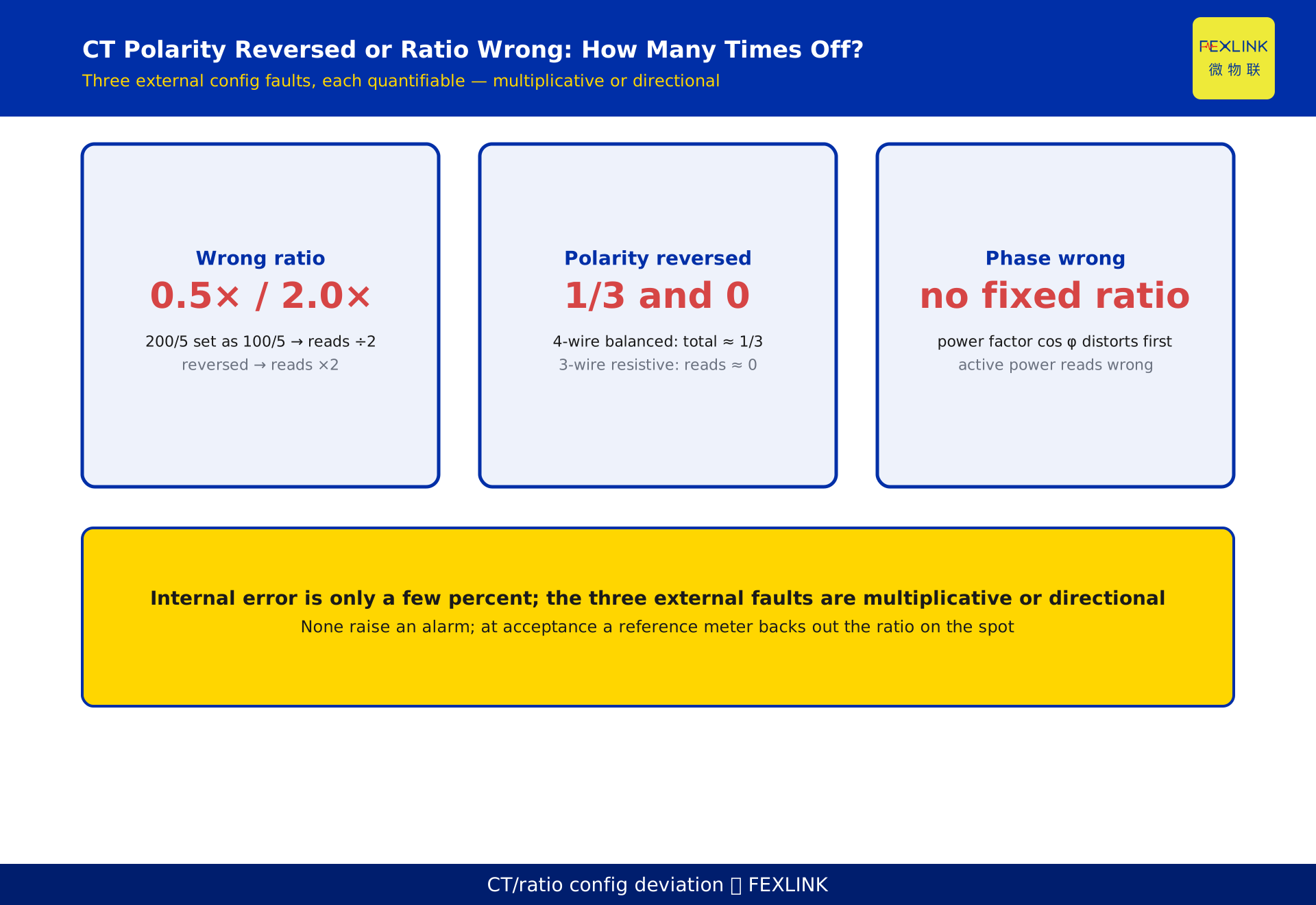
- Wrong ratio setting: the reading scales by configured ÷ actual multiplier. A 200/5 CT read as 100/5 reads exactly half the true value; set the other way, it doubles.
- CT polarity reversed: the secondary current flips 180°, flipping the power sign. A single-phase meter runs backward; a balanced three-phase four-wire meter with one reversed CT reads about 1/3 of true; a balanced three-wire two-element meter stalls near zero.
- Phase sequence wrong (two phases swapped): voltage and current no longer pair as designed, so the power factor (cos φ) distorts first and active power reads wrong too, with no fixed multiple.
None of these raises an alarm; the meter keeps counting, only in the wrong direction or magnitude, and the error is usually found months later. A reference meter on a known load, backing out the multiplier, catches all three on site.
1. First, separate a multiplier problem from a broken meter
A meter measures secondary voltage and current (the small signals after CT and PT transformation) and multiplies by a ratio to get primary-side energy. That ratio depends on two things: the actual transformer ratio, and the ratio configured in the system (or whether the meter applies it at all).
"Energy off by several times" really means only two things:
- The ratio basis does not match — the actual transformer ratio differs from the configured one.
- The phase relationship does not match — polarity or phase sequence is reversed, so power is computed with the wrong sign or pairing.
Neither means the meter is bad; the bookkeeping is wrong. The advantage is that bookkeeping errors are quantifiable and checkable: with the nameplate and a stretch of known load, you can compute exactly how many times off the reading is, without guessing.
2. CT ratio and the multiplier: a wrong setting scales the reading
The multiplier is the product of two ratios:
total multiplier = CT ratio × PT ratio
- CT 200/5 A → ratio 40
- CT 100/5 A → ratio 20
- PT 10 kV/100 V → ratio 100
- Low-voltage circuits usually have only a CT, so the total multiplier is the CT ratio (e.g. 40)
The relation is direct:
primary energy = secondary register increment × total multiplier
If the configured multiplier (K_cfg) differs from the actual transformer multiplier (K_actual), the reading scales:
reading / actual ≈ K_cfg / K_actual
So the error factor = K_cfg ÷ K_actual — a pure proportion, independent of load size or time of day.
3. A wrong ratio: a clean proportional error
Typical case: a CT was replaced, or the nameplate was mistyped during a retrofit, and the system still computes with the old ratio.
- Actual CT 200/5 (40), set as 100/5 (20): K_cfg/K_actual = 0.5, so the reading is half the true value — the monthly energy is silently halved.
- The reverse: actual 100/5 (20), set as 200/5 (40): K_cfg/K_actual = 2.0, so the reading doubles.
- A larger CT (say 400/5 = 80) set as 200/5 reads half.
The signature is clean: a fixed multiple, constant every period. At audit, divide platform by register; if the ratio stably equals a clean 2, 0.5, or 4, it is almost certainly a wrong ratio.
4. CT polarity reversed: power sign flips, meter runs backward or stalls
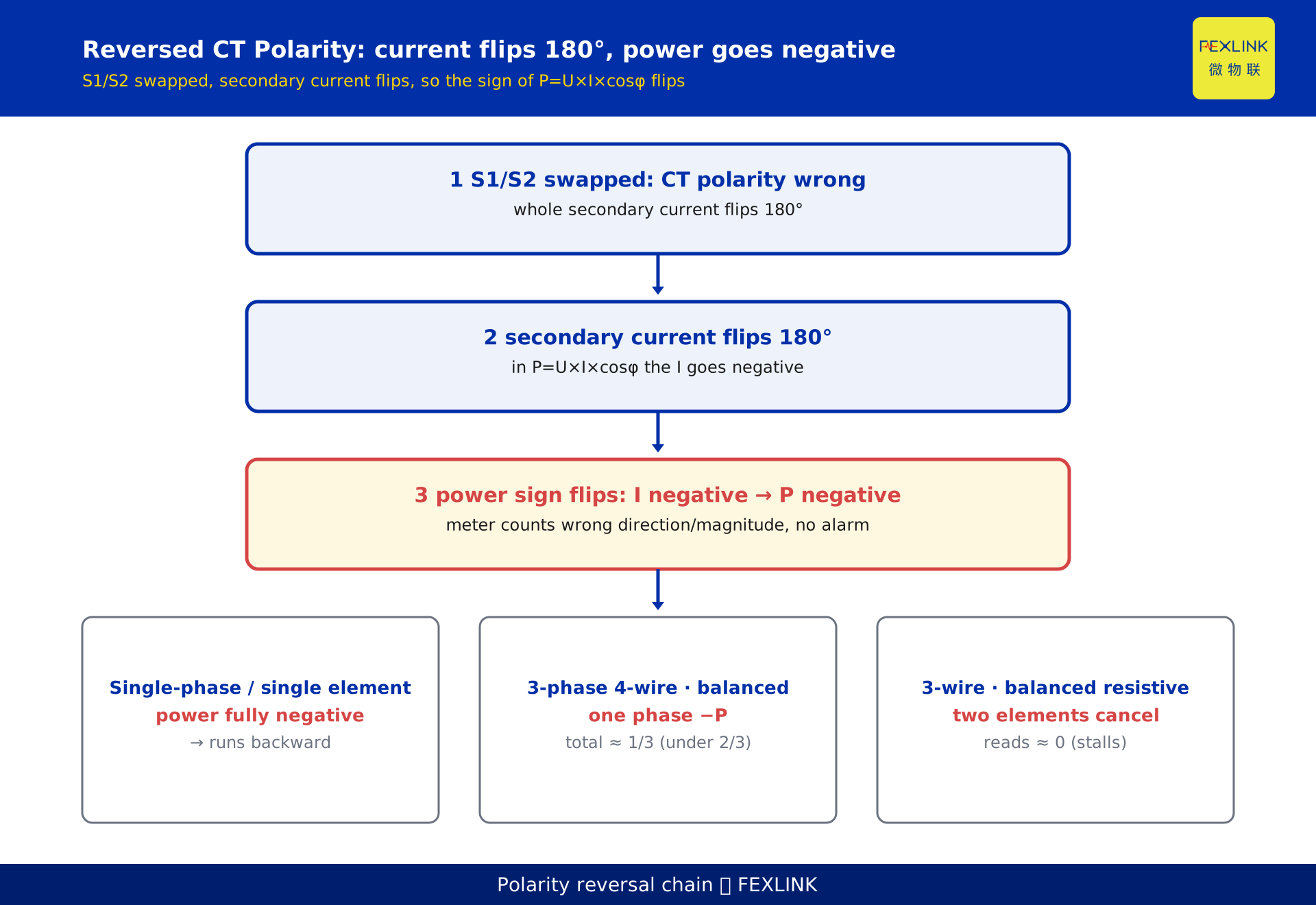
Reversing CT polarity (S1/S2) flips the secondary current 180°. Since P = U × I × cos φ, a negative current makes power negative. The effect differs by wiring:
- Single-phase / single-element: power goes negative, the meter runs backward; a forward-only meter stalls and stops advancing.
- Three-phase four-wire (three elements): the reversed phase goes +P to −P. Under balanced load the total becomes P+P−P = P, so the reading is about 1/3 of true, under-counting by 2/3.
- Three-phase three-wire (two elements): under balanced resistive load the elements cancel and the reading stalls near zero; with reactive or unbalanced load it is an anomalously small or negative value.
The insidious part is the silence in three-phase systems: the meter still turns, but in the wrong direction and magnitude, with no alarm. By the time reconciliation asks why the energy does not add up, months of wrong metering have accumulated.
5. Phase sequence wrong: power factor distorts, active power follows
Wrong phase sequence usually means two phases swapped, or voltage and current sequences disagree. Each element's voltage and current no longer pair as designed:
- The first symptom is a distorted power factor (cos φ) — leading/lagging reversed, or an implausible value (a resistive load reporting a very low cos φ).
- Under balanced resistive load, active power may merely shrink or go negative; but with inductive, capacitive, or unbalanced load, active power also reads wrong, with an unstable error direction.
- So phase sequence has no clean "factor": its signature is power and power factor in disarray, depending on the field wiring group and the load.
This class cannot be caught by the "ratio" test; it is found by the reasonableness of power factor and three-phase power: same circuit, same load, cos φ suddenly wrong → check phase sequence first.
6. A quantitative deviation table for the three faults
| Fault | Nature of error | Quantifiable typical value | Alarms? |
|---|---|---|---|
| Wrong ratio | Fixed proportional | reading = actual × (K_cfg÷K_actual), e.g. 0.5 or 2.0 | No |
| CT polarity reversed (single-phase) | Power negative | Meter runs backward | No |
| CT polarity reversed (4-wire, balanced) | One phase negative | reading ≈ 1/3 of actual (under 2/3) | No |
| CT polarity reversed (3-wire, balanced resistive) | Elements cancel | reading ≈ 0 (stalls) | No |
| Wrong phase sequence | PF distorts + active power varies | No fixed factor; cos φ abnormal first | No |
This table is also the boundary with the "internal meter error" articles: this article covers only external CT/ratio/wiring faults, not the internal sampling, integration, or drift chain. Internal errors are a few percent and stable; the three external faults here are "multiples" or "direction" errors — a different scale, and the highest priority to check.
7. Why these faults stay hidden for months
- No alarm. The meter counts per code; polarity and phase-sequence errors often "look normal" in three-phase systems.
- Stable but unexplained. A wrong ratio is a fixed multiple, easily mistaken for "this customer just uses little"; a polarity error of 1/3 or 0 looks like "light load".
- Found only after the fact. They surface at billing or reconciliation, by which time the error has accumulated for months.
The real fix is to move the check forward to commissioning acceptance, not wait until the books fail.
8. Acceptance check: measure with a known load, back out the ratio
The most effective field method is a reference meter (or portable calibrator) on the same circuit:
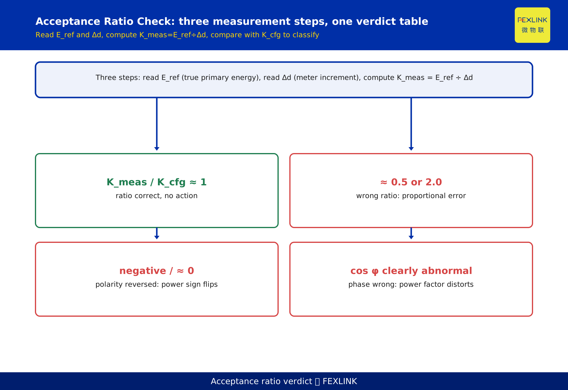
- Read the true primary energy E_ref over a period T — it measures primary side directly, independent of the meter-under-test ratio.
- Record the meter-under-test register increment Δd (secondary side).
- Back out the measured multiplier K_meas = E_ref ÷ Δd.
- Compare with K_cfg: if K_meas / K_cfg ≈ 1 the ratio is right; drift to 0.5 or 2.0 is a wrong ratio; negative or near zero is reversed polarity.
Without a reference meter, a load of known accurate power run for a fixed time gives a rough check: E_known = P × T, then E_known ÷ Δd. The reference-meter method is preferred — it catches polarity (sign) and phase sequence (cos φ) at once, and reports power direction and cos φ directly.
9. Correction steps and the metering ledger
- Check the nameplate first — confirm the actual ratio (e.g. 200/5) and compare with K_cfg; a wrong ratio is located on the spot.
- Confirm the deployment before changing config — apply the ratio in exactly one place (meter or platform) to avoid double conversion off by another factor.
- Check polarity — use the reference meter to read power direction; re-verify each CT's S1/S2 against the meter terminals.
- Check phase sequence — see whether cos φ matches the load; on three-wire meters check the two elements read with the same sign.
- Record in the ledger — write each meter's nameplate, ratio, wiring group, and commissioning result, so next quarter does not re-derive the same answer.
Configuration, acceptance, and verification follow DL/T 448-2016 (Technical Management Code for Electric Energy Metering, current). Accuracy classes, wiring groups, and verification intervals belong to that code and are separate from the deviation computation here.
In practice these settings are managed in a digital electrical supervision system through a metering ledger: each meter's nameplate, ratio, and wiring group are entered once, and acceptance uses a reference meter for a loaded check. ESA all-element smart meters and the ZSA metering module family (e.g. ZSA-22243-R) provide ratio entry and check points at factory and commissioning; specific items and accuracy are per the latest selection manual.
FAQ
Q: Energy suddenly dropped to half — is the meter broken?
Do not replace it yet. The most likely cause is a wrong ratio: actual CT 200/5 but the system computes as 100/5, so the reading is exactly half. A reference meter backs out the multiplier; a 0.5 factor gives it away at once.
Q: A three-phase meter advances very slowly, almost not at all — what could it be?
On a three-wire two-element meter, one CT with reversed polarity under balanced resistive load stalls near zero (the two elements cancel). Confirm with the reference meter's power direction.
Q: The power factor is negative, or plainly wrong — why?
Typically reversed phase sequence or polarity: voltage and current no longer pair as designed, so cos φ distorts first. Check phase sequence and polarity before touching compensation.
Q: Why don't these faults raise an alarm?
They do not change the meter's counting behavior, only the phase or ratio it computes with. The meter metrologies per code; only the direction and magnitude are wrong, with no fault flag of its own.
Q: How do I catch all three quickly at acceptance?
Put a reference meter on the same circuit, back out K_meas = E_ref ÷ Δd, and compare with K_cfg: drift to 0.5/2.0 is a wrong ratio, negative or near zero is reversed polarity, abnormal cos φ is wrong phase sequence.
Q: One reversed phase on four-wire — how far off is it really?
Under balanced load, one reversed phase makes the total read about 1/3 of actual (under by 2/3). Unbalanced load shifts the number, but "clearly low and not returning to normal month over month" is the common tell.
Scope and limitations
- This article covers quantifiable deviations from external CT/PT ratio settings, CT polarity, and wiring phase-sequence errors, for transformer-connected AC energy metering and commissioning acceptance. Directly connected (no transformer) meters have no ratio or polarity stage and are out of scope.
- The 1/3 and near-zero values for "reversed polarity" are derived for balanced load: four-wire one-phase reversed ≈ 1/3 of actual, three-wire balanced resistive two-element cancellation ≈ 0. Real unbalanced or reactive loads deviate and must be confirmed with a reference meter rather than applied directly.
- Wrong phase sequence is not a fixed-factor error; its signature is distorted power factor and active-power readings, with the exact number depending on wiring group and load. No single factor is given.
- The values "200/5, 100/5, 40, 20, 1/3, 0.5, 2.0, K_cfg, K_actual, K_meas, E_ref, Δd" are set or symbolised for illustration and represent no real customer or project; actual ratios and configurations are per field nameplate, meter manual, and system settings.
- Configuration, acceptance, and verification follow DL/T 448-2016 (current); no specific clause is cited, and accuracy classes, wiring groups, and verification requirements are per the code text.
- Descriptions of ESA all-element smart meters, the ZSA metering module family (ZSA-22243-R), and the digital electrical supervision system are per the latest selection manual and product knowledge base; this article is not a selection or procurement recommendation.
Frequently Asked Questions
Energy suddenly dropped to half — is the meter broken?
Do not replace it yet. The most likely cause is a wrong ratio: actual CT 200/5 but the system computes as 100/5, so the reading is exactly half. A reference meter backs out the multiplier; a 0.5 factor gives it away at once.
A three-phase meter advances very slowly, almost not at all — what could it be?
On a three-wire two-element meter, one CT with reversed polarity under balanced resistive load stalls near zero (the two elements cancel). Confirm with the reference meter's power direction.
The power factor is negative, or plainly wrong — why?
Typically reversed phase sequence or polarity: voltage and current no longer pair as designed, so cos φ distorts first. Check phase sequence and polarity before touching compensation.
Why don't these faults raise an alarm?
They do not change the meter's counting behavior, only the phase or ratio it computes with. The meter metrologies per code; only the direction and magnitude are wrong, with no fault flag of its own.
How do I catch all three quickly at acceptance?
Put a reference meter on the same circuit, back out K_meas = E_ref ÷ Δd, and compare with K_cfg: drift to 0.5/2.0 is a wrong ratio, negative or near zero is reversed polarity, abnormal cos φ is wrong phase sequence.
One reversed phase on four-wire — how far off is it really?
Under balanced load, one reversed phase makes the total read about 1/3 of actual (under by 2/3). Unbalanced load shifts the number, but "clearly low and not returning to normal month over month" is the common tell.