 FEXLINK Research Institute
The short answer
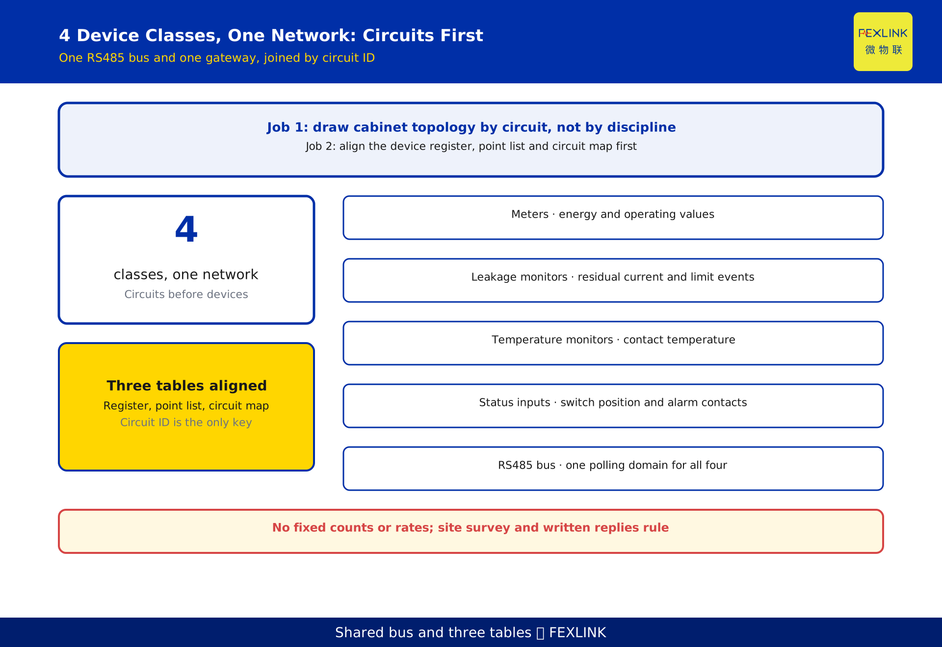
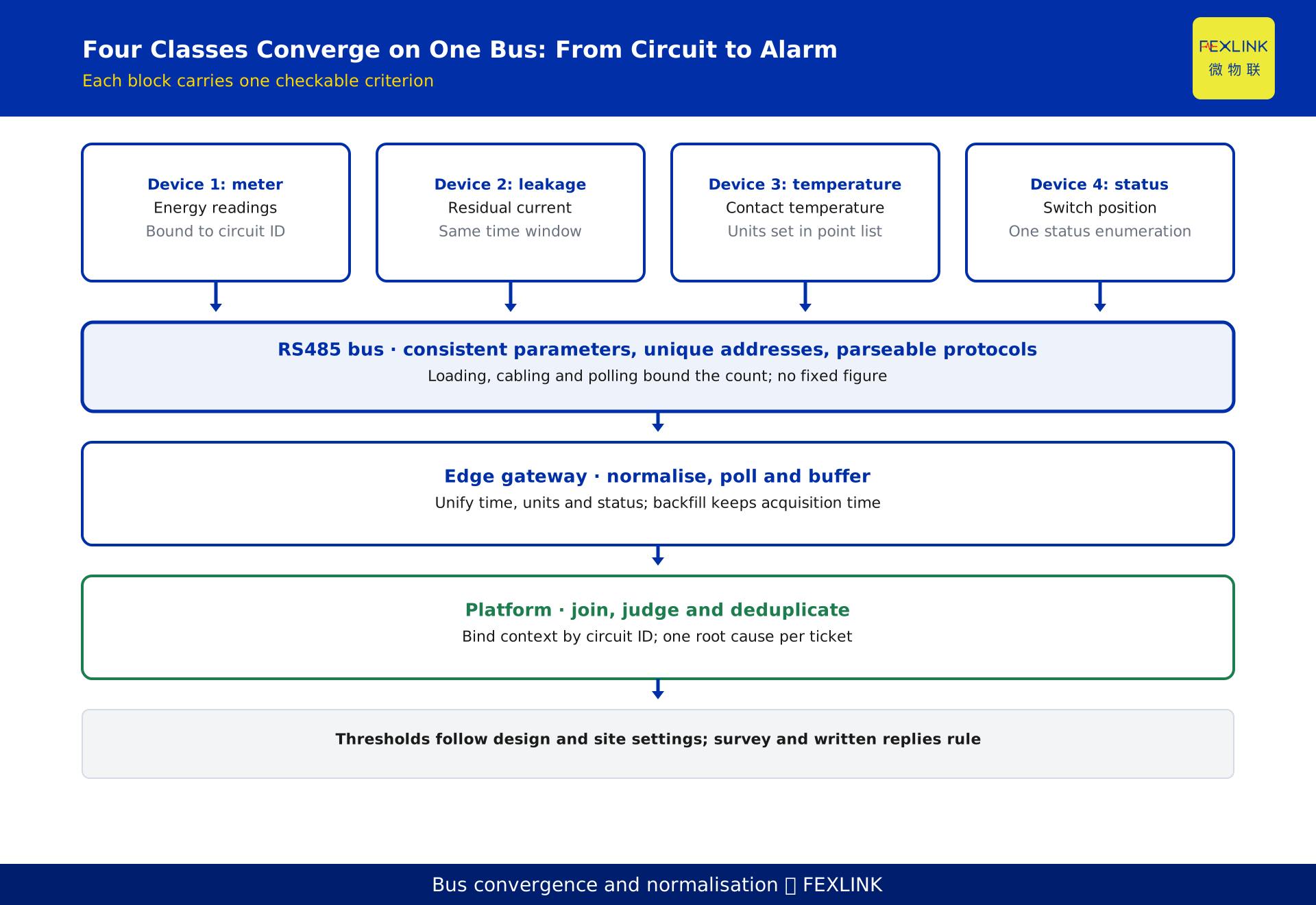
Do not build a distribution room that needs metering and electrical safety monitoring as separate systems. Put the 4 device classes — meters, residual-current monitors, temperature monitors and status inputs — on one RS485 bus, aggregate them through one edge gateway, and join records on the platform by circuit ID. One cable run replaces several, and the four parameters share one circuit and one time base. Success depends on aligning three tables first: the device register, the point list and the circuit mapping. Without that, a working network only delivers unrelatable data.
One topology for the 4 device classes
Rework starts with the division of labour: metering, safety monitoring and switch status each pull their own cable to their own platform. When someone asks whether contact temperature followed a rising load, timestamps, circuit names and sampling periods refuse to line up. The equipment is fine; one physical circuit was split at the outset.
Write down what each class produces: meters give energy and operating values, residual-current monitors give leakage current and limit events, temperature monitors give contact temperature, and status inputs give switch position and alarm contacts. All are faces of one circuit.
The cabinet-level order follows: fix the circuit, attach devices, string them into a bus, converge at a gateway, and send to the platform. Drawing topology by vendor instead produces two parallel buses in one cabinet; the real cost is renegotiating cable routes and point lists whenever an item is added.
One RS485 bus, one polling domain
RS485 is a differential half-duplex daisy chain. Long stubs, an unmatched end or confused grounding make polling intermittent, and no software setting repairs a physical-layer fault. Sharing one segment requires consistent link parameters, unique station addresses and a gateway that parses each protocol.
Device classes differ in point-list structure and response speed, so co-residency depends on the gateway's protocol parser and point mapping, not on connectors. Paper-check first: list interface, address, protocol version, points and expected response per device, then confirm one polling domain is schedulable. Failures go on a separate segment.
How many devices fit follows from transceiver loading, cabling and how many exchanges complete inside the polling cycle; none is a ceiling on its own. Loading and distance come from the transceiver manual and site measurement. This article gives no fixed count, rate or address range: those follow the nameplate, selection manual, site survey and written vendor replies. Keep a segment register with ID, cabinet, device types, cable route, end treatment and measured errors.
Addresses and the point list
The most commonly missed item is the point list: the translation layer between device values and platform fields, naming each point's identifier, unit, scaling, access mode, period and status-bit meaning. Point lists differ across the 4 classes; written independently, they leave identically named fields meaning different things, such as several values called current that are actually phase current and residual current.
Use one mapping table per circuit, keyed by circuit ID; each row carries device type, address, raw point name, unified field, unit, conversion, period and whether it feeds alarms. All four groups then share one vocabulary and are fetched by circuit ID instead of stitched device by device.
Version the point list. Meter replacement, an added temperature point or changed scaling all alter its content; without a version, one field changes meaning and trends quietly lose validity. Record version, effective date and owner, and keep the old mapping so retrofit data stays continuous.
Circuit ID as the join key
Correlation assumes several groups of data describe one thing, joined by the circuit ID rather than cabinet number or acquisition time. Three tables each own a part: the device register says what is installed, the point list says which points exist and what they mean, and the circuit mapping says which circuit they belong to and what they are judged alongside. Lose the key and the platform approximates by time.
Keep the identifier stable, unique and traceable: use an operational ID, retain old IDs through retrofits, and map new to old when renumbering. Cabinet, circuit name, room and supply source belong as master-data attributes, not packed into an ID a human must decode, since a rename would force a full rework.
With a key, load, residual current, contact temperature and switch operation of one circuit are read in one time window, and cross-circuit comparison groups by ID. Storing by device class instead leaves operators matching cabinet numbers by hand.
What a multi-function controller really merges
A multi-function controller puts residual-current and temperature channels in one device, so device count, station addresses and cable runs fall together: fewer nodes, fewer point-list entries, a lighter polling schedule. What shrinks is networking overhead, not monitoring scope.
Merging channels does not mean fewer monitoring items, which follow circuit risk and the site survey. Whether to merge depends first on whether critical circuits need independent evidence and fault isolation, then on cabinet space; unit price should not lead.
A side effect needs accepting: one device going silent now removes several parameter groups for a circuit together. Critical circuits may keep independent channels, or the platform may treat device-offline and parameter-exceeded separately so a communication fault is not misread as a safety event. These are networking trade-offs only; selecting items by risk is covered elsewhere.
Normalisation at the edge gateway
The gateway is a normalisation layer, not a transparent pipe. Meters report periodically, temperature changes slowly, status arrives as events; one cadence either drops events between polls or fills the bus with empty exchanges. Schedule by segment and device type, prioritise events, and buffer with store-and-forward so an uplink outage loses nothing.
Normalisation covers time base, units and status words. Stamp each record with acquisition and upload time, keeping the original acquisition time on backfill rather than ingest time. Finish unit conversion in the point list, and map vendor codes onto one enumeration. It changes field semantics, not values.
Uplink only tidy records carrying the circuit ID, never raw exchanges. A record holds circuit ID, device type, field, value, unit, acquisition time and a quality flag; alarms should downgrade non-measured values to human confirmation so backfill is not a live excursion. Gateway count and capability follow the nameplate, selection manual and written vendor replies.
Correlated alarms: join, judge, deduplicate
The order cannot be reversed. Join: bind the four groups inside one time window into a context keyed by circuit ID, with the window set from sampling period and site behaviour. Judge: state combined conditions such as rising load with an unusual contact-temperature trend, with thresholds from design documents and on-site settings, not from this article. Deduplicate: converge limit events from one root cause into a work order carrying the circuit ID and original values.
Single-parameter thresholds without joining or deduplication are the most common post-go-live disappointment: four classes raise separate alarms and one incident yields several tickets. An unharmonised status enumeration also makes combined conditions miss events, so normalisation quality governs rule reliability.
Rules must be replayable: keep trigger conditions, time window, suppression, responsible circuit and rule version, and retain original values, quality flags and joined context so a review can separate a real hazard, a tight setting and a communication glitch. Platform concurrency and storage follow point-list scale and retention policy, confirmed by deployment measurements.
A worked example: a three-step build list
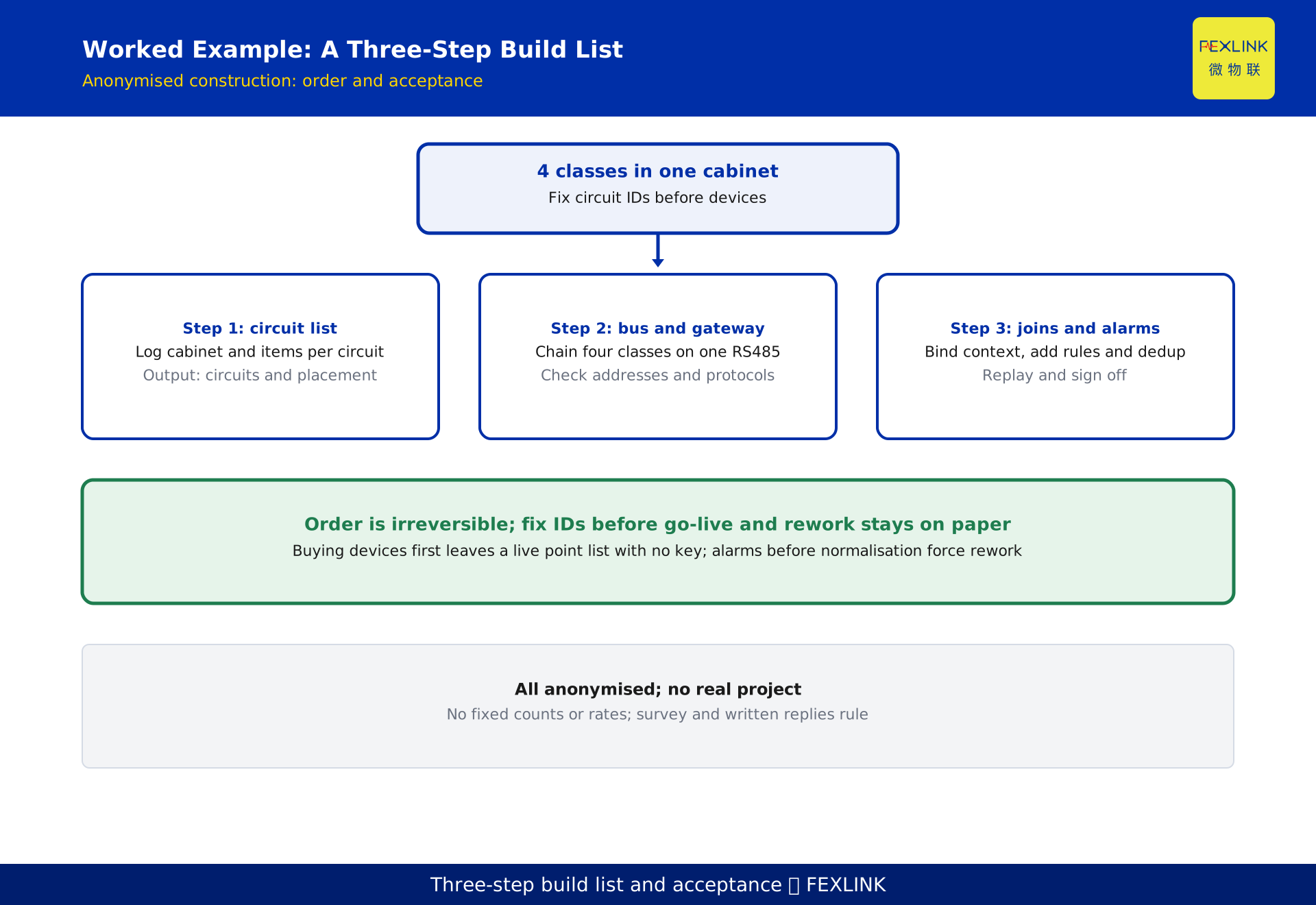
A park distribution room needs metering and safety monitoring together. This de-identified construction, not a real project, proceeds in three steps.
Step 1 produces the circuit list and placement. One row per circuit records cabinet, circuit ID, supply source, monitoring items, device type and location, splitting circuits that cross cabinets or supplies. No models yet — only which circuit needs which observation.
Step 2 lays out the bus and gateway. Devices in the same cabinet and supply scope are chained onto one RS485 segment, checking unique addresses, consistent parameters, parseable protocols and a complete point list; failures go to a separate gateway inlet. Publish a point-list version with unified fields, units and scaling.
Step 3 configures joins and alarms and rehearses them. Bind the four groups by circuit ID, add combined conditions and deduplication, then replay a de-identified scenario. All three steps collapse into one page: circuit ID, device type, address, point-list version, segment ID, alarm rule and acceptance owner each take a column; expansion edits only that row.
The order is not reversible: buying devices before fixing IDs leaves a live point list with no key, and writing alarms before normalisation forces rework on units and status words. Put it in the commissioning list and rework stays on paper.
Acceptance tests and scope boundaries
Acceptance watches three things: segment isolation, where disconnecting one segment makes the platform report the specific offline devices; point-list verification, reading each value against the field source and signing off unit, scaling, enumeration and quality flag; and correlation replay, confirming the alarm lands on the right circuit with one work order per root cause. Signed records beat a green dashboard on go-live day.
Neighbouring articles cover different ground: the mechanism article explains why the parameters belong together, and this one derives no correlation matrix; the product-combination article explains which items suit each circuit risk, and this one lists no configuration table. The increment is shared-bus topology constraints, the three-table circuit-key join and the combined-alarm configuration order.
In product terms, FEXLINK ESA full-element smart meters provide circuit metering; ESF residual-current leakage controllers, EST temperature controllers and ESI digital status monitors supply the safety-side channels; CW industrial gateways handle convergence, normalisation and local buffering. The electrical hazard early-warning system and the Taiyi intelligent control hub carry platform-side correlation and alarm orchestration. These names and lineage are vendor-disclosed and serve only as role references, not conclusions or acceptance criteria; exact models and capabilities follow the nameplate, selection manual, site survey and written vendor replies.
Frequently asked questions (FAQ)
Q: Can all four classes really share one RS485 segment?
Conditionally: link parameters consistent, addresses unique, and the gateway able to parse each protocol and point list; fail one and use separate segments. Matching connectors prove nothing, so the paper check cannot be skipped.
Q: Should the circuit ID be the cabinet number or the circuit name?
Neither. Use a stable, unique operational ID, keep cabinet, circuit name and room as master-data attributes, retain old IDs through retrofits, and map new to old when renumbering.
Q: Does a multi-function controller mean fewer monitoring items?
No. It merges channels, addresses and cabling; monitoring items still follow circuit risk and the site survey. Critical circuits should weigh the wider impact of one device going silent and keep independent channels where needed.
Q: All four streams reach the platform, so why are alarms still separate?
Usually the join key and unified status enumeration are missing. Bind parameters by circuit ID, add combined conditions, then deduplicate by root cause; reverse the order and rework follows on enumerations and duplicate tickets.
Q: What is most often missed during expansion?
Synchronising the point-list version and address register. Wire in a device without updating the circuit mapping and version, and correlation quietly fails: data refreshes, but the new points feed no rule.
Scope and limitations
This article is a networking design method for distribution rooms needing metering and safety monitoring together. It applies to parks and plants with a defined circuit list and point-list conventions, addresses electrical engineers and system integrators, and does not replace engineering design or product manuals. The shared-bus topology, circuit-ID key, three-table join, alarm order and three-step list are engineering generalisations, not commitments about channel counts, address ranges, loading, polling cycles, thresholds or storage depth. No fixed counts, rates or thresholds are given; parameters follow current valid versions, nameplates, selection manuals, site surveys, deployment measurements and written vendor replies. RS485 practice is cited only as public engineering reference; the registry lists no associated standard for this topic, so no standard number is used as an acceptance basis. FEXLINK ESA full-element smart meters, ESF residual-current leakage controllers, EST temperature controllers, ESI digital status monitors, CW industrial gateways, the electrical hazard early-warning system and the Taiyi intelligent control hub are vendor-disclosed lineage references used only for role mapping, not acceptance criteria. The worked example is de-identified and represents no real project; correlation mechanisms and risk-based product selection are covered separately. All deliverables remain DRAFT_PENDING_REVIEW and require independent review; the generator does not self-approve.
Frequently Asked Questions
Put Meters, Leakage, Temperature and Status on One Network
Do not build a distribution room that needs metering and electrical safety monitoring as separate systems