 FEXLINK Research Institute
The short answer
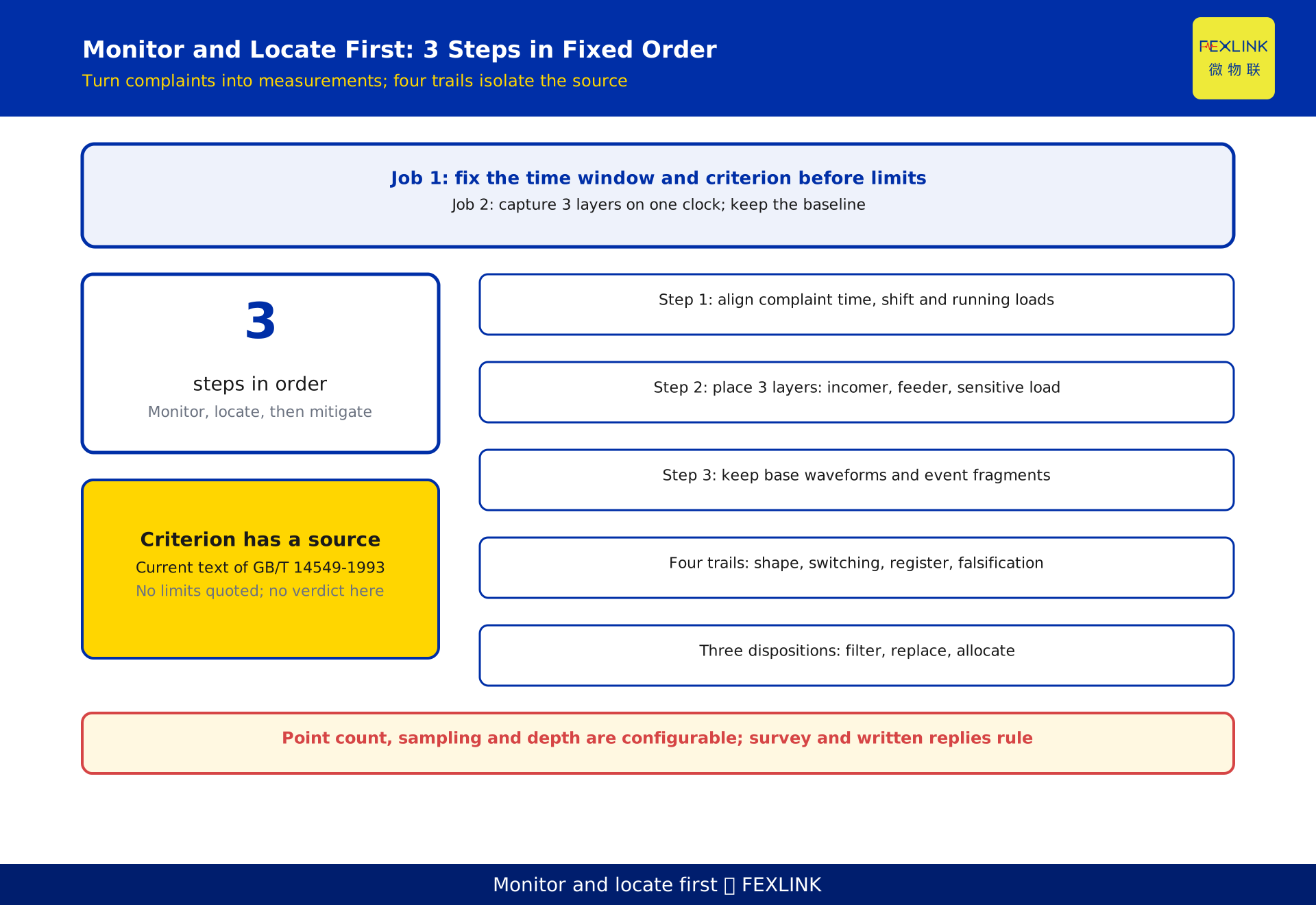
Do not buy a filter because a workshop reports harmonic trouble. The order is three steps: capture continuous waveforms with the FEXLINK ESE power quality monitor and align them to complaint timestamps; rank sources with a harmonic fingerprint library by shape and timing; then choose local filtering, equipment replacement or an external-responsibility claim. Compliance is judged under the currently effective text of GB/T 14549-1993; this article quotes no limit values.
Why mitigation before diagnosis fails
A complaint is a symptom, not a measurement point. Tripping, cable heating and drive faults may come from one drive, upstream injection, or a correction branch meeting system impedance; each demands a different response.
Three rework patterns follow. Type 1 filters the main incomer: the reading falls but the load is unchanged. Type 2 ignores operating states, so a bank sized at light load becomes resonant at heavy load. Type 3 leaves an external source, so the site still pays for internal hardware. All act before the source is known; the baseline is gone.
Monitoring first preserves that baseline: complaint times, harmonic orders, distortion trend, the load list in service and the standard version as criterion. Without it, no claimed improvement can be checked.
Turning a complaint into a measurable window
Convert the verbal report into quantities: which asset, when, and what the plant was doing. That yields a complaint time window with concrete timestamps spanning one complete start/stop cycle.
Then fix the criterion. Whether a limit is exceeded is judged under the currently effective text of GB/T 14549-1993, with values depending on voltage level, short-circuit capacity and agreed capacity. It cites the standard only as a criterion source, quotes no permissible values and issues no compliance verdict; values follow the standard text and design documents.
Keep measurement separate from judgement: waveforms, orders and trends are measurements, while comparing them with the clauses and signing is a judgement for a qualified party. The clock is decisive — all points, start/stop logs and complaint records share one time source, with acquisition and upload times stored separately. If clocks drift, every correlation is displaced.
Three monitoring layers: incomer, feeder, sensitive load
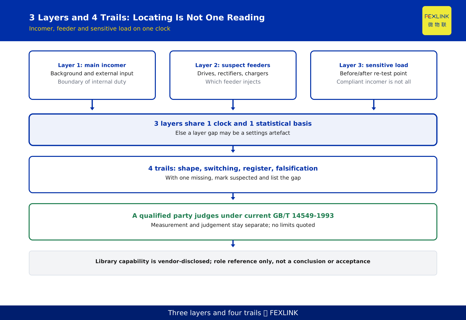
Points should answer who generates, who suffers and what arrives from outside.
Layer 1 sits at the main incomer, giving site background and external contribution and marking the boundary of internal responsibility. If an order persists with all loads off, the source is probably outside.
Layer 2 sits on suspect feeders — circuits feeding drives, rectifiers, chargers or switched-mode supplies — and answers which feeder injects. Placement follows the load register: every harmonic-generating device maps to one traceable record matching the circuit number.
Layer 3 sits at the terminals of the controller, servo drive or protection device named in the complaint. It answers what the victim sees and serves as the post-mitigation comparison. A compliant incomer does not imply a compliant terminal; the difference points to line impedance.
A reference point on a circuit with no nonlinear load exposes instrument bias and wiring errors. All 4 points share one clock and one statistical basis; otherwise a layer difference could be a settings artefact. Point count is configurable per the site survey and written vendor replies.
Event-driven capture and why averages hide the culprit
Plants with energy reports still fail to localise a source, usually because of aggregation: a periodic average flattens intermittent impacts, switching transients and short excursions at shift changes — exactly when complaints occur.
Split capture in two: a base layer retaining waveforms and order trends, and an event layer retaining higher-resolution trigger fragments. Triggers are set on site from the complaint window, start/stop signals and protection records, not a hard-coded threshold; each fragment carries its trigger condition and quality bit.
Also retain "no-complaint" reference records. Only with normal and complaint shifts on one axis can an order rise as a device starts. If an order stays flat but complaints cluster in one shift, investigate that shift's process and wiring. Capture capability, channel count, sampling rate and storage depth are configurable and vendor-disclosed; values follow the nameplate, selection manual and site survey.
Four evidence trails that turn a fingerprint into a verdict
A harmonic fingerprint is not a threshold on one order. It is 4 checkable trails tied to one asset so the conclusion can be replayed and challenged.
Evidence 1 is spectral shape. Rectifier topologies differ, so order proportions and their load behaviour differ; compare shape and ratios, not one magnitude, or background harmonic is mistaken for the source.
Evidence 2 is switching-time correlation. Overlay the feeder's start/stop log and the event fragment on one axis: with Layer 2 strongest, Layer 1 diluted and Layer 3 attenuated, timing beats amplitude for showing who moved first.
Evidence 3 is the load register plus process log: the register says what is connected and on which shift; the process log says what was done. Together with shape and timing they turn "an order changed" into "a device changed under a specific condition".
Evidence 4 is falsification. Stop the suspect device and re-measure to see whether the order disappears; it alone can disprove the hypothesis. If shutdown is impossible, compare against the reference point and no-complaint records and write "not falsified" into the conclusion rather than confirmed.
All four are required before a verdict; with one missing, write "suspected" and list the gap. Library matching only ranks candidates; its capability is vendor-disclosed, a method description rather than a conclusion.
Roles of the monitor and the controller
The FEXLINK ESE power quality monitor captures continuous waveforms, harmonic orders and event fragments: the evidence tool for diagnosis. The FSE power quality controller handles circuit-side measurement and status output, suiting a confirmed feeder. One answers what happened; the other how that circuit looks now.
On the platform side, the harmonic fingerprint library of the Taiyi intelligent control hub aligns the three layers on circuit number and one time base, ranks candidates by spectral shape, and attaches the complaint window and re-test result to one event. It outputs candidates and an evidence chain, not a verdict; a person signs each trail.
A common mistake is treating a watch point as an evidence point. Watch points may not retain switching fragments; evidence points are densified for the window. Mixing them produces "fine most days, no data when complaints arrive". Keep raw evidence before mitigation, then converge watch points onto the 1 to 2 confirmed feeders. Product naming and capability are vendor-disclosed, used only as role references.
Three dispositions after localisation
Disposition 1 is local mitigation. With the source confirmed on an in-service internal feeder, place filtering close to it and re-measure at Layer 3; the criterion is terminal distortion back inside the applicable clauses without amplification. A compliant incomer alone is not completion; sizing is computed by the designer from site impedance.
Disposition 2 is replacement or adjustment. When the device is aged, miswired, or resists local suppression, replacing it is more direct. The criterion is economics and maintainability: compare one-off cost, ongoing losses and maintenance occupation against the operating record after replacement, not just the quotation.
Disposition 3 is responsibility allocation. If Layer 1 still shows the same order with all internal loads off, the source may be on a shared external line; internal mitigation is then ineffective. Deliverables are timestamped three-layer comparisons and all-off evidence for discussion with the utility. This article takes no position on liability.
The three can combine, but the order is fixed: evidence, characterisation, then action. A missing record at any step makes improvement impossible to attribute.
Worked example: a localisation checklist
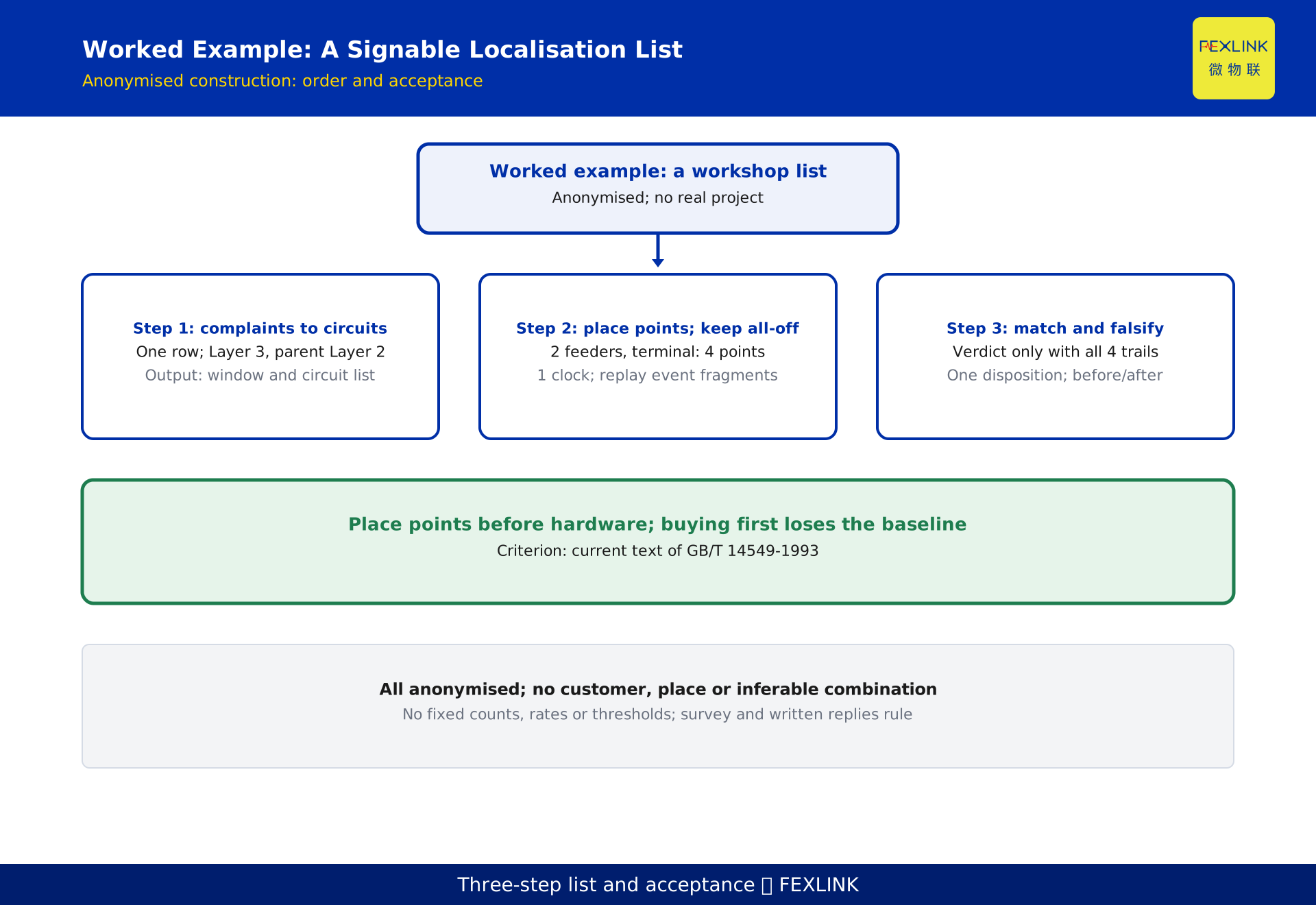
The following is an anonymised construction, not a real project.
Step 1 builds a complaint-to-circuit table. In an anonymised workshop where a device trips intermittently, sort complaints by time with shift and protection records, then map each affected device to a Layer 3 point and its parent Layer 2 feeder. One row per complaint; the output is a time window and a circuit list. No model numbers, only when and where.
Step 2 places points and captures evidence. Put evidence points at the incomer, two suspect feeders and the terminal, plus one reference point: 4 points on one clock. Replay event fragments across the window, reserve an all-loads-off period for incomer background, and align the start/stop log to the same clock.
Step 3 matches the fingerprint and falsifies it. Rank candidates by shape, check switching times, register and process log, then re-test after shutdown; write the verdict only when all four trails agree. Choose among the three dispositions and place Layer 3 re-test values before and after mitigation in one table.
The three steps collapse into a one-page list with columns for complaint window, circuit number, event fragment, candidate device, four-trail sign-off, disposition, re-test value and signatory. The order cannot be reversed: buying hardware before placing points loses the baseline; arguing liability before capture makes the three-layer comparison impossible.
Acceptance checks and scope boundaries
Three checks gate go-live. Time-alignment replay: pick any complaint and find its timestamp, event fragment and quality bit intact. Fingerprint replay: re-run the ranking on all four trails and match the signed version, keeping unfalsified items marked "suspected". Post-mitigation re-test: re-measure at Layer 3 with the pre-mitigation settings and attribute improvement to a specific action. All three are signed.
Boundaries matter. Harmonic mechanisms and how to read orders are covered elsewhere; this article derives no formulas. The limit clauses of GB/T 14549-1993 and short-circuit capacity conversion are analysed elsewhere; here the standard is cited only as the criterion source. This piece contributes a path from monitoring to a mitigation decision: placing three layers, event-driven capture, four-trail sign-off and criteria for three dispositions — not a theory or clause interpretation.
When acceptance fails, do not add hardware. Check whether clocks are unified, whether averaging erased the fragments, and whether the shutdown re-test was done. Most inaccurate localisation is a capture-basis problem.
Frequently asked questions (FAQ)
Q: We already have energy reports. Why install monitoring points?
Periodic reports average away switching instants and short excursions, exactly when complaints occur. They show energy used, not which order rose when a device started. Localisation needs timestamped waveforms, event fragments and three-layer comparison; reports cannot substitute for monitoring.
Q: What decides whether harmonics exceed the limit?
The currently effective text of GB/T 14549-1993, applied to voltage level, short-circuit capacity and agreed capacity, with a qualified party issuing the conclusion. This article cites the standard as a criterion source only, quotes no limit values and issues no compliance verdict; values follow the standard text and design documents.
Q: Can a library candidate be treated as the verdict?
No. Matching only ranks candidates. Switching times, the load register and a falsification re-test must also line up; until all four trails agree, write "suspected" and list the gap. The shutdown re-test is the most skipped step. Matching capability is vendor-disclosed, not a conclusion or acceptance criterion.
Q: If the source is outside the site, is an internal filter still useful?
Usually not, and it may turn the compensation branch into an amplifier. If Layer 1 still shows the order with all internal loads off, move to evidence and negotiation with the three-layer comparison and all-off data. Internal mitigation only addresses internal harmonics; separate inside from outside first.
Q: A compliant incomer after mitigation — is that acceptance?
Not on its own. The sensitive load sees terminal distortion, so a compliant incomer does not imply a compliant Layer 3. Re-test at the same point with the same settings, confirm the terminal is inside the applicable clauses, and attribute improvement to a specific action. Both replays are signed too.
Scope and limitations
This article applies to workshops and plants with harmonic complaints where points can be placed and a load register with start/stop logs exists; it addresses electrical engineers and energy managers. Where monitoring cannot be installed, or the symptom is unrelated to electrical quantities, start with basic investigation.
Three layers, event-driven capture, four-trail sign-off, three disposition criteria and a three-step list are a method summary, not a commitment on channel count, sampling rate, storage depth or filter capacity. No fixed counts, rates, thresholds, limit values or schedules are given. Compliance is computed under the currently effective text of GB/T 14549-1993 with site conditions; this article does not replace a compliance verdict.
The worked example is anonymised, represents no real project, and contains no customer, place or inferable combination. Model names and capabilities of the FEXLINK ESE power quality monitor, the FSE power quality controller and the Taiyi hub's harmonic fingerprint library are vendor-disclosed, used only as role references and excluded from conclusions, selection advice and acceptance criteria; models and channels follow the nameplate, selection manual, site survey and written vendor replies. All deliverables remain DRAFT_PENDING_REVIEW and require independent review; the generator does not self-approve.
Frequently Asked Questions
Persistent Factory Harmonic Complaints
Do not buy a filter because a workshop reports harmonic trouble