 FEXLINK Research Institute
The short answer
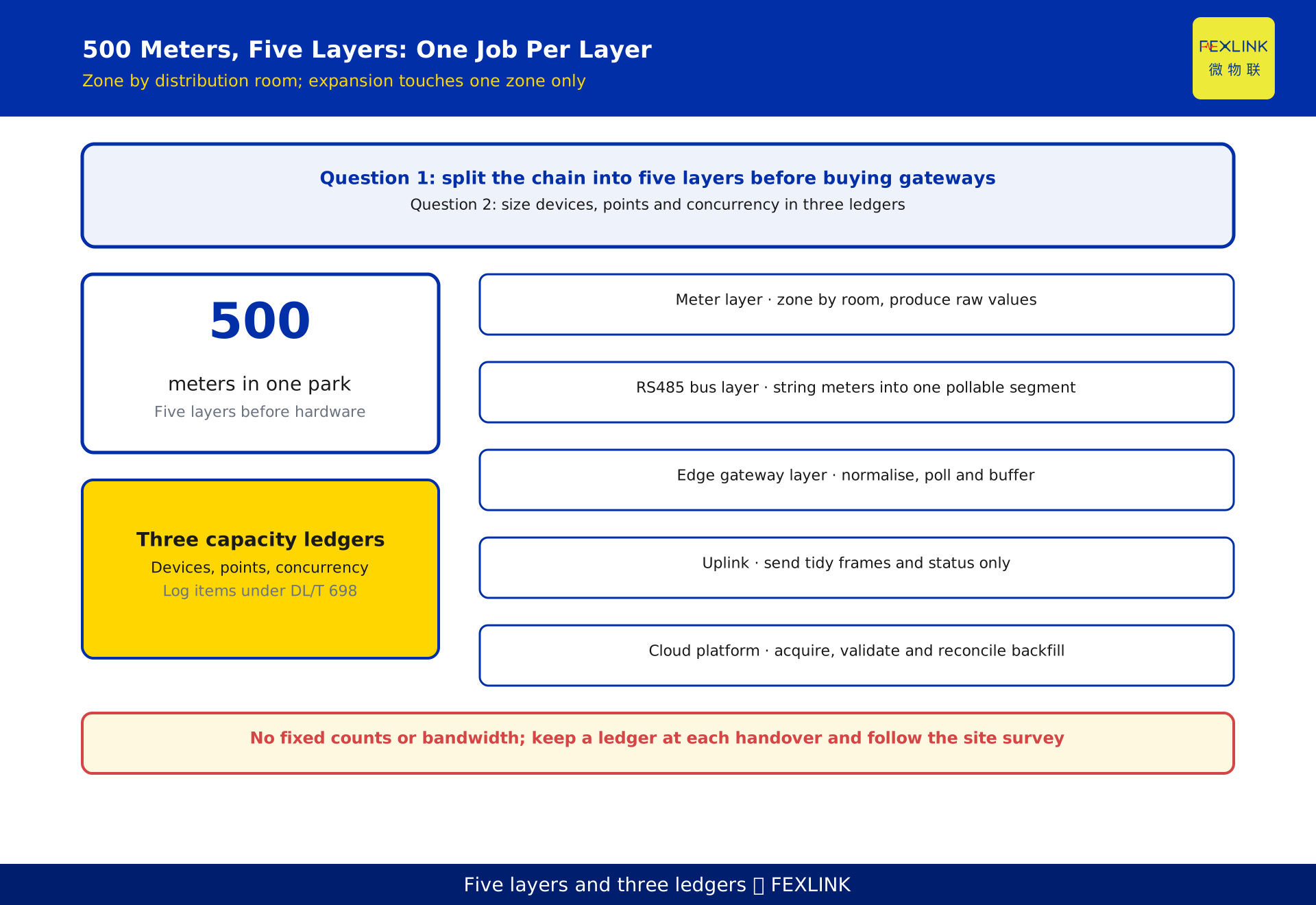
For a park with 500 meters, do not start by deciding how many gateways to buy. Split the chain into five layers: meters, RS485 bus aggregation, edge gateways, uplink, and cloud platform. Zone the site by distribution room, give each zone one bus group and one gateway, aggregate the uplinks, and let the platform handle central acquisition and validation. Size capacity through three separate ledgers rather than a guess: devices, points, and concurrency. Then expansion touches only the affected zone instead of forcing a new topology.
Five layers: turning 500 meters into an accountable chain
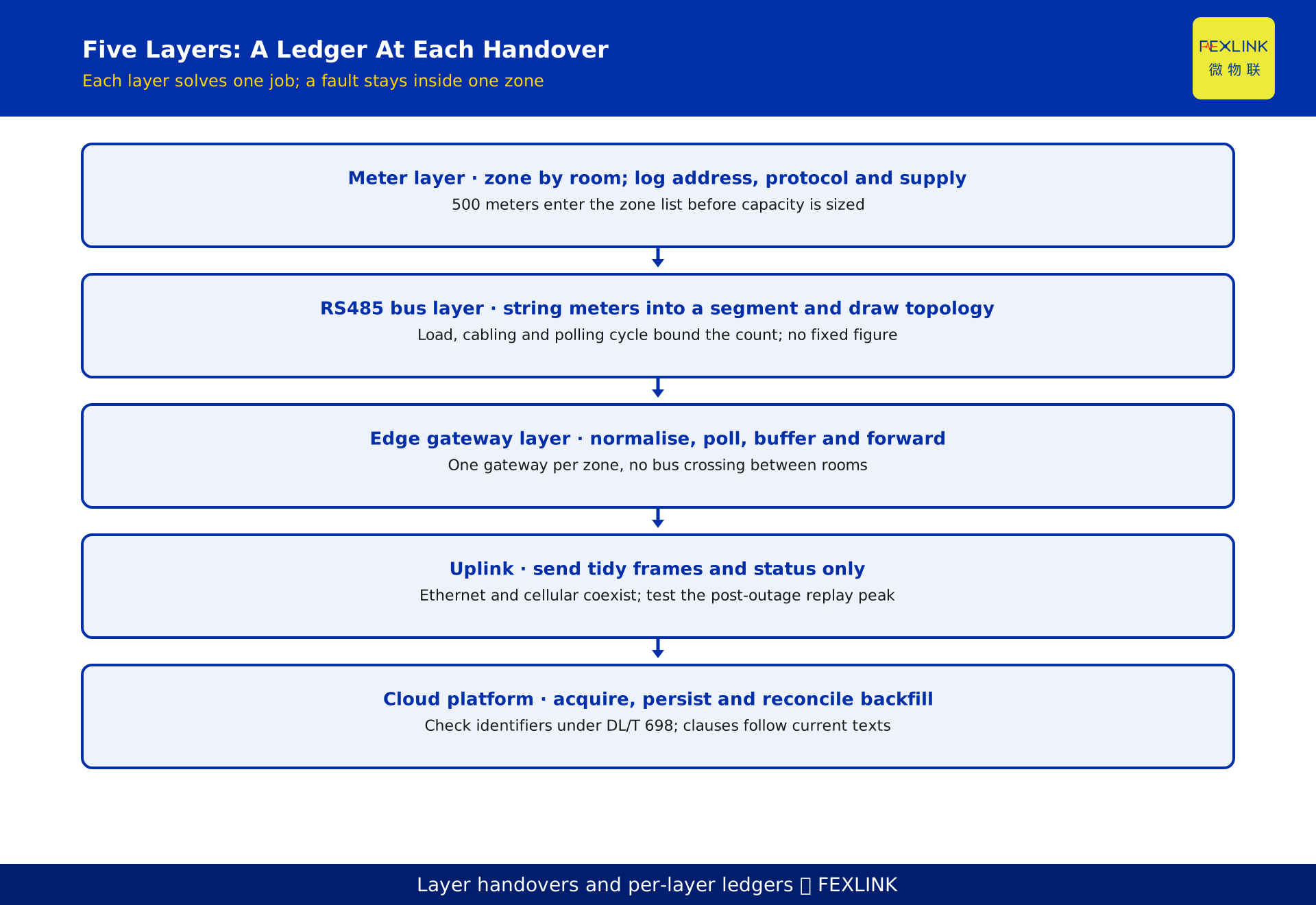
At scale, the common mistake is treating automatic meter reading as two steps: meters to gateway, gateway to platform. There are five layers, each solving a distinct problem with its own capacity and failure record. The meter layer produces raw measured values. The bus layer strings meters in one physical area into a pollable segment. The gateway layer normalises protocols, schedules polling and buffers locally. The uplink carries consolidated data to the server room or cloud. The platform acquires, validates, stores and serves data.
The layering is not a diagram for a review meeting; it defines three handover interfaces. Between bus and gateway sits the question of how many devices share one segment. Between gateway and uplink sits how much data must move per unit time. Between uplink and platform sits whether concurrent acquisition and writes can keep up. Keep a ledger for each, and expansion decisions become explicit.
Meter layer: zone by distribution room, fix the physical boundary first
Zones follow physical boundaries, not meter counts. Meters in one distribution room, one cabinet and one supply feeder naturally belong together; Start with a room list and record room identifier, cabinet position, meter count, supply source and available cable route, then decide where a separate zone is needed.
Record communication resources at the same time: interface type, address, protocol version, baud rate, parity, and whether the segment is shared with another system. Address collisions and protocol mismatches stay invisible during single-meter commissioning and surface at once when many meters share a segment. Address, rate and parity form one link parameter set and must be consistent along the whole segment; values follow meter nameplates, protocol manuals and the site survey.
Bus layer: what limits the number of meters on one RS485 segment
RS485 is a differential half-duplex bus, normally wired as a daisy chain. The planning action at this layer is therefore narrow: keep each segment within a controllable boundary and draw its topology explicitly.
Three things jointly limit how many meters a segment can carry: transceiver load capability, cable length and installation quality, and how many request-response exchanges fit inside the polling cycle. None of them can be used alone as a ceiling. Node count and distance follow transceiver manuals and field measurement; this article gives no fixed count. Keep a segment ledger instead: identifier, zone, attached meters, cable route, termination, measured errors and retries, each item verifiable.
DL/T 698 and similar public protocol series help organise data items and object identifiers so meters in a zone are read under one definition. Clauses and versions follow current texts and device manuals; the reference implies no product capability.
Gateway layer: one gateway per zone, never across rooms
Gateway placement follows the same rule: one gateway per zone, installed in or near that zone's cabinet, with no bus crossing between rooms. Concentrating gateways in a single room appears to save hardware but drags several long buses to one point, enlarging both cabling complexity and the blast radius of a single installation fault.
This layer performs three checkable jobs: schedule polling per segment, normalise different protocols into one data model, and buffer and forward during uplink outages. All are configurable items; actual capability follows nameplates, selection manuals, site surveys and written manufacturer replies, and is not a fixed specification in this article. Gateway quantity is therefore not total meters divided by a constant. It is zone count plus a per-segment capacity check: start from the zone count, then examine any zone with many attached meters to see whether it needs a second segment or another gateway.
Uplink: absorb bandwidth pressure at the edge
The key uplink decision is what to send. The cloud should receive standardised data assembled by the gateway, not every raw exchange from every segment. Once normalisation and local preprocessing happen at the edge, the uplink carries only tidy frames and status reports, and bandwidth no longer scales linearly with meters.
Uplink technology follows site conditions: zones with reliable wired infrastructure use the park Ethernet, while scattered or hard-to-wire locations use cellular mobile networks. Both can coexist in one park behind a common gateway-side egress. Technology and bandwidth follow the site survey and operator availability; no fixed figure is given here. The heaviest moment is when every gateway reconnects at once and replays its buffer, so acceptance testing should reproduce that scenario rather than measuring only steady-state operation.
Platform layer: acquisition, buffering, and backfill are separate duties
The platform is often described as one action, yet it holds three independent duties. Central acquisition receives reports under a unified object model, aligns timestamps, checks completeness, and flags missing, duplicate or out-of-order data. Buffering and persistence isolate high-frequency ingest from analytical reads so reports cannot slow acquisition. Backfill reconciliation verifies replayed data by zone and time window after an outage, marking gaps instead of silently filling them.
Each duty has its own acceptance test. Acquisition checks whether all zones are complete at a common instant. Persistence checks for queueing and dropped frames under peak writes. Backfill checks whether the ledger can be cleared item by item after replay. Platform sizing depends on point-list size, collection frequency and retention policy, and must be measured in the deployment environment; no fixed capacity is given here.
Capacity headroom: device, point, and concurrency ledgers
Capacity is not one division but three ledgers. The device ledger counts addressable devices on a segment and decides whether to split segments or add gateways. The point ledger counts independently readable and writable data points per device and multiplies by device count, setting the acquisition load on gateways and platform. The concurrency ledger counts how many acquisition and backfill actions overlap at a given instant, setting peak pressure on uplink and platform writes. Each ledger has its own limit, and exceeding any one of them causes trouble that the others cannot compensate for.
Reserve headroom in the same order: count devices from the room list, count points item by item, then estimate concurrency from collection frequency and outage replay, documenting the reason for each allowance. Headroom is an explainable allowance for future zones and retry traffic; ceilings follow device manuals and load tests, with no fixed coefficient given here. An adjacent article covers single-node capacity estimation as device count times points per device; here it is only one ledger inside an overall layering. The sequence is to set zones and segments with the five-layer structure, validate each zone with the single-node method, then return to the concurrency ledger for uplink and platform.
Worked example: a layered plan for a 500-meter park
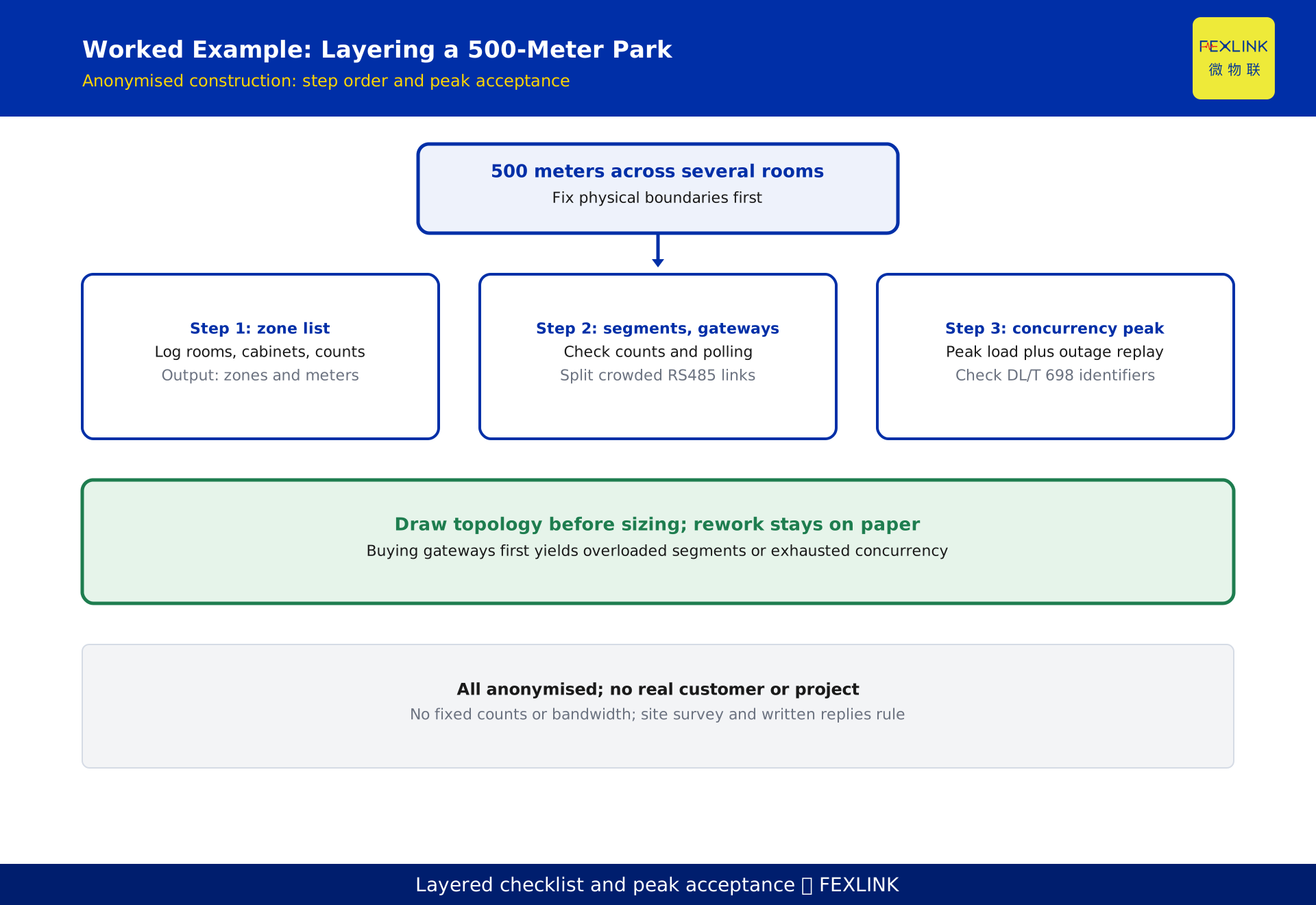
A park has 500 meters spread across several distribution rooms. The following sequence is a desensitised construction and represents no real project.
Step 1 builds the zone list. Record rooms, cabinets, meter counts and cable routes, and separate meters that sit across buildings or supply sources. The output is a zone count and a meter count per zone.
Step 2 assigns segments and gateways. For each zone, check meter count, point-list length and polling cycle, then decide whether one segment suffices. Zones with many meters get a second segment or an additional gateway; uplink type is chosen per zone from local conditions. Everything is entered in the segment ledger.
Step 3 returns to the concurrency ledger for uplink and platform. Treat all zones collecting simultaneously and a post-outage bulk replay as two peak scenarios, verify remaining uplink and write headroom, and write the three acceptance tests into the commissioning checklist. The checklist becomes one sheet with a row per zone covering segment, gateway, uplink type, point-list version and acceptance owner, so expansion edits only the affected row.
The order matters. Buying gateways before zones are drawn tends to produce enough gateways but overloaded segments, or healthy segments but exhausted concurrency. Drawing topology before sizing keeps rework on paper.
Where products fit, and the boundary with adjacent articles
In product terms, the FEXLINK ESA all-element smart meter regularises raw measured values at the meter layer, the ESX intelligent edge computing gateway handles protocol normalisation, polling and local buffering at the gateway layer, and the FEXCloud IoT cloud platform receives central acquisition, validation and data serving at the platform layer. These names and this lineage are enterprise-disclosed and serve only as role comparison, not as conclusions or acceptance criteria. Specific models, interfaces, load and capacity follow nameplates, selection manuals, site surveys and written manufacturer replies.
Three boundaries separate this article from its neighbours. Single-node capacity estimation answers how to compute device count times points per device; this article answers how zones, segments, uplink and platform are laid out for a 500-meter site. Post-commissioning dropout diagnosis locates lost connections; this article covers topology and capacity before build. Cross-vendor protocol diagnosis handles unreadable or garbled data; here the zone list only reserves columns for addresses and protocol versions, with no frame-level debugging. The increment is the overall method of grouping buses by distribution room, keeping a ledger at each of the five interfaces, and accepting uplink and cloud against peak scenarios, rather than a capability list for any device.
Frequently Asked Questions (FAQ)
Q: How many gateways does a 500-meter park actually need?
Not the total divided by a constant. Set zones by distribution room, use one gateway per zone as a baseline, then check segment load and polling cycle in dense zones and split or add where needed.
Q: How many meters can share one RS485 segment?
Transceiver load, cable length and installation quality, and the exchanges fitting the polling cycle constrain it together. Node count and distance follow transceiver manuals and field measurement; no fixed count is given here.
Q: Must every uplink use wired Ethernet?
No. Wired zones can use park Ethernet and scattered ones cellular; both may coexist behind a common egress. The choice follows the site survey, and the post-outage replay peak must still be tested.
Q: If the gateway already buffers data, does the platform still need backfill reconciliation?
Yes. Gateway buffering prevents loss while the uplink is down; platform reconciliation checks for missing, duplicated or timestamp-mismatched replay data. Without item-by-item clearance, a silent gap can survive a successful replay.
Q: Which step must not be skipped during expansion?
Rechecking the concurrency ledger. A new zone also adds pressure from every gateway reconnecting and replaying at once, so rerun the peak scenarios at the enlarged scale.
Scope and limitations
This article is a pre-build layering method for automatic meter reading systems at sites with a large meter population, intended for system integrators and park energy managers where distribution rooms, cabinets and a meter inventory are already defined. It does not replace engineering design, cabling codes, current standard texts or product manuals. The five-layer structure, zoning by distribution room, the three capacity ledgers and the three-step checklist are generalisations of engineering practice, not promises about the load capability, port count, concurrent connections, bandwidth or storage depth of any model. No fixed values are given for meters per segment, bandwidth, point ceilings or headroom multipliers; parameters follow current effective versions, nameplates, selection manuals, site surveys, deployment measurements and written manufacturer replies. RS485 bus practice and the DL/T 698 series are public or compliance references only, with clauses following the formal texts. The FEXLINK ESA all-element smart meter, ESX intelligent edge computing gateway and FEXCloud IoT cloud platform are enterprise-disclosed lineage used for role comparison only, not as an acceptance basis. The worked example is desensitised and represents no real customer or project; single-node capacity estimation, dropout diagnosis and cross-vendor protocol misreads are separate articles. All deliverables remain DRAFT_PENDING_REVIEW and require independent review; the generator does not self-approve.
Frequently Asked Questions
A Park with 500 Meters
For a park with 500 meters, do not start by deciding how many gateways to buy