 FEXLINK Research Institute
The short answer
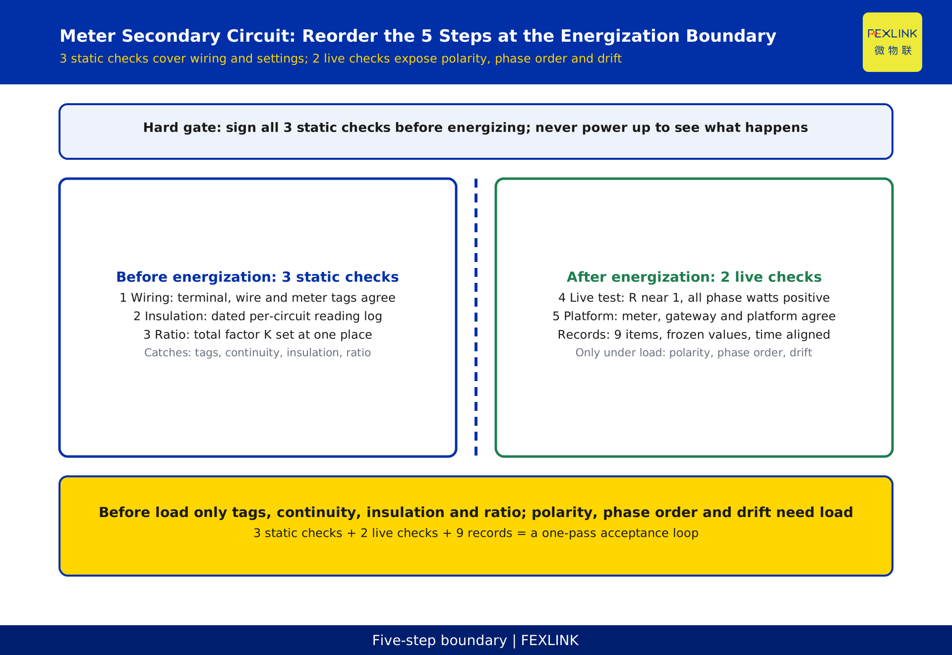
Getting a secondary circuit right the first time means giving each of five steps one pass/fail criterion. Wiring: drawing terminal numbers, wire marks and meter labels agree, and the CT secondary loop has no break. Insulation: every circuit has a recorded reading meeting the limits in current documents. Ratio: the multiplier chain is applied in exactly one place. Live load: the meter's primary current divided by a clamp-meter reading is about 1. Integration: meter face, gateway and platform all trace to one source. Markings, continuity, insulation and ratio settings close before energisation; polarity, phase sequence and reading errors appear only under load. Schedule three static checks plus three live checks.
1. Where the Five Steps Split: What Is Catchable Before Energisation
Method statements often promise to catch polarity, ratio and phase-sequence errors before energisation. That is half true. Four things can be closed with the power off: polarity markings, loop continuity, insulation condition, and the ratio setting with its multiplier chain.
Reversed polarity shifts the secondary current phase; continuity testing sees nothing. A phase-sequence error pairs voltage with the wrong current; the loop stays continuous and insulation sound. Both appear only under energised load, as negative per-phase power, distorted power factor, or a main meter disagreeing with sub-meters. Signing them off early defers the two hidden faults to post-commissioning reconciliation.
So the five steps split at the energisation boundary. Steps 1, 2 and 3 are static checks before power; Steps 4 and 5 are live checks after power. Put a hard gate at the boundary: no energisation until all three static checks are signed. Step 4 needs a stable load window with a clear power factor. The technical management framework follows current DL/T 448-2016, Technical administrative code of electric energy metering; no clause numbers are quoted here.
2. Step 1 - Wiring De-energised: Three Documents Must Agree
Isolate, prove dead and tag before touching secondary wiring. With the primary live, an open CT secondary induces a dangerous voltage, so short it reliably and keep one earth point before disconnecting. No fuse, switch or other device that could open the loop belongs in that circuit.
Wire to the subtractive polarity convention: primary P1 and P2 and secondary S1 and S2 terminals must match the drawing, with current entering the meter from S1 and returning through S2. Voltage and current samples must come from the same circuit and the same phase; on a three-phase meter, never infer phase identity from wire colour.
Three pass criteria: drawing terminal numbers, wire marks and meter or terminal-block labels agree point by point, with every cell of the comparison table ticked; continuity from S1 through the meter current loop to S2 reads low resistance with no intermediate break and no temporary shorting link left behind; and each phase's samples are logged against one circuit number.
3. Step 2 - Insulation Testing: Disconnect Electronics First
A megger applies high DC voltage: disconnect meters, acquisition modules, gateway and communication cables, then discharge the circuit. Leaving electronics connected causes many dead-port callouts. The order is fixed: disconnect, measure, restore, then verify.
Measure current loop to earth, voltage loop to earth, and between loops, reading each circuit separately. No acceptance value is given here: limits differ by voltage class and insulation construction, so take them from the current construction acceptance code, the verification regulation and the manufacturer's manual, and copy them into the site work instruction.
Three pass criteria: every circuit has a dated reading with circuit number and instrument ID; readings of the three phases are close, and an outlier sends you to damp terminals, damaged insulation or shielding earth before blaming the meter; and every shorting link, earth and temporary disconnect is restored and counter-signed afterwards.
4. Step 3 - Ratio Setup: Set the Multiplier in Exactly One Place
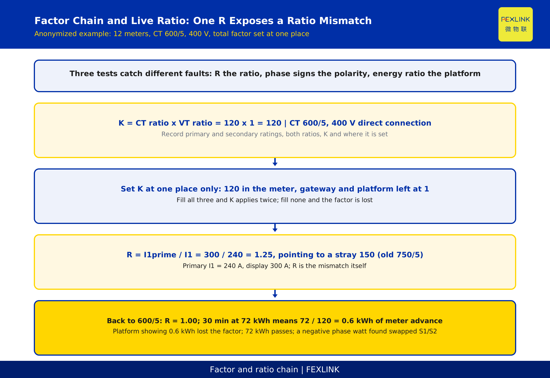
One multiplier chain: K equals the CT ratio times the voltage transformer ratio. With low-voltage 400 V fed directly, the voltage side contributes 1 and K is just the CT ratio; only voltage-transformer-fed circuits need both ratios multiplied.
Ratio can usually be set in three places: meter parameters, the gateway or collector point table, and a platform multiplier field. Filling all three multiplies twice; filling none drops the multiplier. The most hidden case is a point table inheriting the previous batch's ratio.
Three pass criteria: draw the multiplier chain listing primary and secondary ratings, both ratios, K and where K is set; leave exactly one place active and mark the other two "not set, treat as 1" in the point-table notes; then recompute from the on-site nameplate. File it before the energisation gate.
5. Step 4 - Live-Load Test: One Ratio and Three Checks
In the chosen window, measure primary current I1 with one clamp meter at the same instant as reading the meter's displayed primary current, then compute R as displayed current over I1. R of about 1 clears the magnitude check. When R is not 1, R itself is the misconfiguration factor and points straight to the wrong ratio.
R checks magnitude only. Two more criteria run alongside: per-phase active power is positive and totals match the scale from I1; per-phase power factor fits the load and the per-phase sum equals total active power. Reversed polarity shows up as a negative in the first; a phase-sequence error shows up as an odd per-phase power factor in the second, and either can leave R looking normal. All three must pass.
Tolerances come from the on-site calibration device and current regulations; no percentage is given here. The window must have stable load, real active power and non-zero power factor. With no load or pure compensation, per-phase active power approaches zero and a signature proves nothing.
6. Step 5 - Platform Integration: Physical, Link, Then Platform
Fix the integration order as physical layer, link layer, platform layer. Physical layer: A/B polarity, terminating resistor, single-point shield earth, unique addresses. Link layer: baud rate, protocol consistency, point-table mapping and units. Platform layer: one multiplier field, aligned timestamps, frozen curves and correct backfill after an outage. The ESA full-element smart meter reads and records per circuit, the ESX edge computing gateway aggregates and uploads, and the digital electrical intelligent supervision system turns readings into ledgers and curves. They provide traceable data, not a verification certificate.
Four pass criteria: every meter reads successfully with unique addresses and one record each; meter face value, gateway raw value and platform converted value at one instant trace to the same source, differing only by that single multiplier conversion; platform frozen values match the meter's own frozen values with aligned timestamps; and one outage-to-recovery drill confirms the alarm fires and backfill creates no duplicated energy.
7. A Sanitised Example: Acceptance Records for 12 Meters
All numbers below are constructed and describe no real customer, project or quotation. A park distribution room adds 12 meters. The CT nameplate reads 600/5, giving a ratio of 120; low-voltage 400 V is fed directly, so the voltage side is 1 and K is 120. Step 3 writes the chain in the meter, with gateway and platform marked "not set, treat as 1".
The load window is stable at power factor 0.90. The clamp meter reads 240 A on the primary, which at 120 implies 2.0 A on the secondary, yet the meter displays 300 A, so R = 300 / 240 = 1.25. Working back from 1.25 shows a factor of 150 was applied; the point table indeed carried the previous batch's 750/5. Restoring 600/5 gives a displayed 240 A and R = 1.00. In the same window a reference meter records 72 kWh on the primary over 30 min, so the register increment should be 72 / 120 = 0.6 kWh. A platform showing 0.6 kWh has dropped the multiplier; 72 kWh passes. Per-phase records show one phase negative, traced to S1 and S2 swapped; after correction all three read positive. All four records enter the acceptance sheet before Step 4 is signed.
Three criteria catch three faults: R catches ratio, the per-phase sign catches polarity, and the energy ratio catches the platform multiplier.
8. Five Rework Traps That Get Missed
First, a shorting link left after an insulation test stops the meter and gets misread as a dead meter; Second, testing with meters and gateway connected damages communication ports yet reads as integration failure. Third, setting the multiplier in meter and platform inflates readings by K, looking like a wrong CT selection. Fourth, a live test on an unloaded or capacitive circuit gives near-zero active power and verifies nothing. Fifth, checking only the total meter hides a reversed phase.
9. Acceptance Handover: Nine Records, None Optional
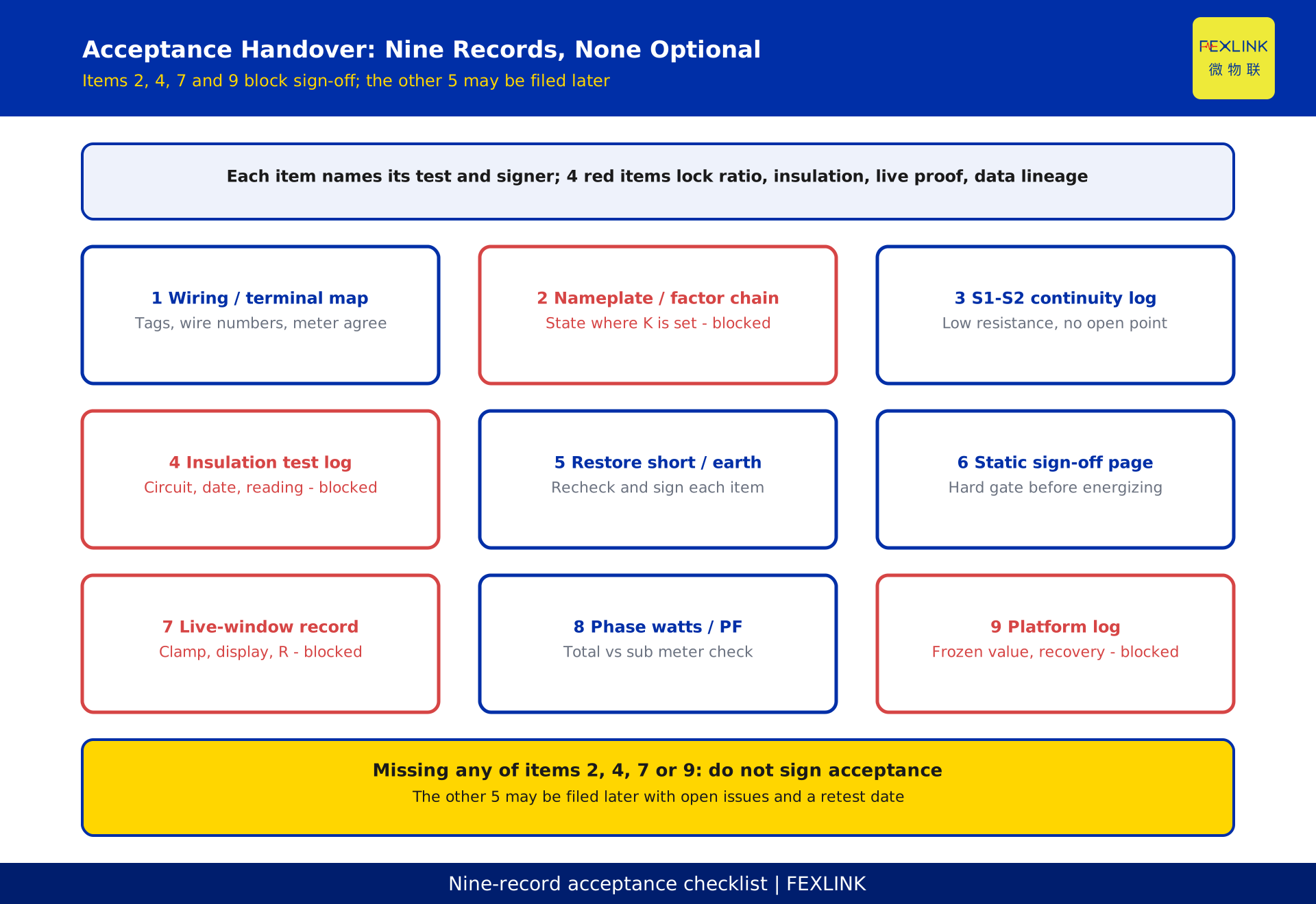
Each item names its criterion and signatory: 1, secondary wiring drawing and terminal comparison table, ticked point by point; 2, nameplate transcription and multiplier chain, including where K is set; 3, full-path continuity record from S1 to S2; 4, insulation readings with circuit number, date and value; 5, counter-signed restoration of shorting links and earth points; 6, the signed pre-energisation static-check conclusion; 7, live-window record with load type, power factor, clamp reading, meter reading and R; 8, per-phase active power and power factor records plus main-versus-sub-meter reconciliation; 9, platform integration records covering the point table, frozen values, outage recovery and the three-source reading, with open issues and a recheck date.
Decision rule: do not sign acceptance if any of items 2, 4, 7 or 9 is missing. They lock the multiplier source, insulation evidence, live verification and data lineage, the only raw material recomputable in a dispute. The other five can be supplied later; these four cannot be back-signed. This article replaces no clause, verification or utility acceptance.
FAQ
Q: Why can a CT secondary circuit not have a fuse or a switch?
With the primary live, an open secondary induces a dangerous voltage and stops measurement. Protection comes from sound wiring, shorting and one earth point, not from a device that can open the loop. Temporary shorting links must be removed and verified before energisation.
Q: What insulation reading is acceptable?
No value is given here. Limits differ by circuit and equipment, so use the current acceptance code, verification regulation and manufacturer's manual. More important is complete recording and three-phase comparison: an outlier points to moisture, damaged insulation or shielding earth before a faulty meter.
Q: Should the ratio be set in the meter, the gateway or the platform?
Any one place works, but only one may be active: set K there and mark the other two "not set, treat as 1" in the point-table notes. Filling all three multiplies twice, filling none drops the multiplier, and inheriting an old value is most hidden, so recompute from the nameplate.
Q: The meter shows 25% more current than the clamp meter. Is the meter faulty?
Do not replace it yet. That ratio is the misconfiguration factor: R = 1.25 means 150 was applied where 120 was correct, and restoring the nameplate value fixes it. A faulty meter is the last hypothesis. Quantifying a reversed CT belongs to the companion article on deviation calculation.
Q: All five steps passed, yet main and sub-meters disagree months later. Why?
The five steps verify wiring, ratio, direction, pairing and data lineage at handover. They cannot cover CT ageing, a shifted load mix, later rewiring, an edited point table or differing rounding conventions. Diagnose those with the companion article on operational variance; the five-step records are its baseline.
Scope and limitations
This article covers secondary-circuit commissioning at acceptance for CT-connected low- and medium-voltage metering. It excludes high-voltage cubicle tests, transformer commissioning tests, verification, sealing and utility acceptance. DL/T 448-2016, Technical administrative code of electric energy metering, was issued on 2016-12-05, took effect on 2017-05-01 and replaced DL/T 448-2000 in full. Only its management framework is cited; no clause numbers or accuracy-class tables are reproduced. Insulation limits, tolerances and verification intervals follow current documents; no specific values are given.
The 12 meters, 600/5 and 750/5, 120 and 150, 240 A and 300 A, 30 min, 72 kWh, 0.6 kWh and power factor 0.90 are constructed examples, sanitised and free of customer, place, project and quotation names. Real acceptance uses the on-site nameplate, verification records and measured data. The ESA full-element smart meter, ESX edge computing gateway and digital electrical intelligent supervision system are described qualitatively; models, ranges and interfaces are customisable per the latest selection manual. None replaces a verification conclusion.
Companion boundaries are fixed: the deviation article quantifies wrong ratio, polarity and phase sequence; the error-chain article covers sampling through to kWh; the operational-diagnosis article classifies platform-versus-meter-face differences; the usage-classification article separates billing from management metering. This article covers only the five pre-handover steps, their pass criteria and the acceptance records. Status is DRAFT_PENDING_REVIEW: an independent reviewer must confirm it before publication, and the author may not self-approve.
Frequently Asked Questions
Why can a CT secondary circuit not have a fuse or a switch?
With the primary live, an open secondary induces a dangerous voltage and stops measurement. Protection comes from sound wiring, shorting and one earth point, not from a device that can open the loop. Temporary shorting links must be removed and verified before energisation.
What insulation reading is acceptable?
No value is given here. Limits differ by circuit and equipment, so use the current acceptance code, verification regulation and manufacturer's manual. More important is complete recording and three-phase comparison: an outlier points to moisture, damaged insulation or shielding earth before a faulty meter.
Should the ratio be set in the meter, the gateway or the platform?
Any one place works, but only one may be active: set K there and mark the other two "not set, treat as 1" in the point-table notes. Filling all three multiplies twice, filling none drops the multiplier, and inheriting an old value is most hidden, so recompute from the nameplate.
The meter shows 25% more current than the clamp meter. Is the meter faulty?
Do not replace it yet. That ratio is the misconfiguration factor: R = 1.25 means 150 was applied where 120 was correct, and restoring the nameplate value fixes it. A faulty meter is the last hypothesis. Quantifying a reversed CT belongs to the companion article on deviation calculation.
All five steps passed, yet main and sub-meters disagree months later. Why?
The five steps verify wiring, ratio, direction, pairing and data lineage at handover. They cannot cover CT ageing, a shifted load mix, later rewiring, an edited point table or differing rounding conventions. Diagnose those with the companion article on operational variance; the five-step records are its baseline.