 FEXLINK Research Institute
The short answer
A 0.5S meter only guarantees ±0.5% under reference conditions — for the meter itself. What actually decides whether your recorded energy is right is an error chain: CT/PT sampling → ADC synchronous sampling → metering-chip integration → ratio conversion. Every stage has a magnitude, and the one most likely to run out of control is the last hop — the ratio and wiring phase. Even the most accurate meter reads off by a factor of two (×2) the moment the CT ratio is set wrong. When calibrating, selecting, or accepting a meter, spend your effort on the CT ratio and phase sequence outside the meter; the payoff dwarfs any fuss over the meter's own 0.5%.
1. Whose accuracy is the meter's accuracy, really
Many people read "0.5S meter" as "the energy it measures is within ±0.5%." That is only half true. The 0.5S class (along with 0.5, 1, and 2) is an accuracy class that GB/T 17215 assigns to the meter body itself, under reference voltage, reference temperature, and a defined current range. It constrains the instrument, not the whole path from the primary-side wiring to the final energy figure.
The bill is based on how much energy the primary side actually used. What the meter reads is the value after transformer scaling, digitized sampling, algorithmic integration, and ratio conversion. The meter body is just one link. This is why two meters both rated 0.5S can show readings tens of percent apart on site: the problem is usually not the meter, it is outside it.
2. How voltage and current enter the meter: CT/PT scaling
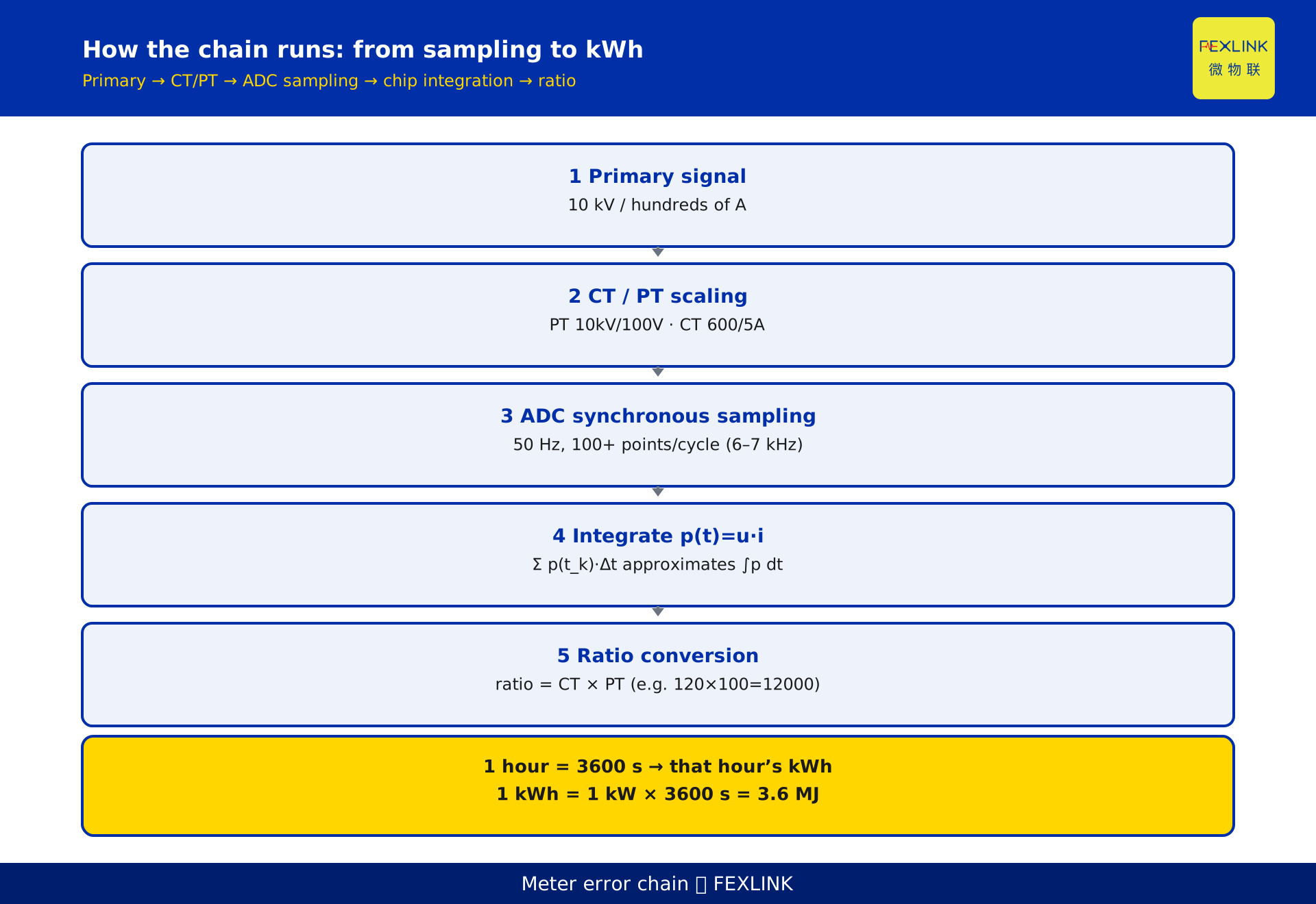
Primary voltage can reach 10 kV or more and current can reach hundreds of amperes — far too large to feed a metering chip directly. A voltage transformer (PT) and a current transformer (CT) first scale the signals down to safe low voltage and low current: PTs commonly 10kV/100V, CTs commonly 600/5A or 400/5A.
This scaling is the first ring of the error chain. Transformers have accuracy classes too — a current transformer of class 0.5 has a basic error limit around ±0.5% under reference conditions (public data / GB/T 20840 family). Its error adds to the meter's, it does not override it. More importantly, the transformer ratio must match the ratio set inside the meter — and, as we will see, a mismatch here can dwarf the 0.5%.
3. AC synchronous sampling and instantaneous power
The scaled signal is a continuous sinusoid. The metering chip samples it synchronously. The grid runs at 50 Hz, a 20 ms period; the chip takes a number of samples per period (illustratively over one hundred per period, roughly a 6–7 kHz rate — check the device manual for the exact figure), and the voltage and current channels must be sampled strictly in sync, or the instantaneous power comes out wrong.
Instantaneous power is p(t) = u(t) · i(t). For AC, only the active component matters; the chip extracts the in-phase part of u and i through a multiplier and a low-pass filter to get instantaneous active power. The error here comes from sampling-clock jitter, inter-channel phase error, and quantization noise, and is usually small (illustratively ≤0.1%) — but if synchronization is done badly, the error grows.
4. How the chip integrates instantaneous power into kWh
Integration is "summing power over time." The chip multiplies each sampling interval's instantaneous power by the sampling period Δt and accumulates:
E = Σ p(t_k) · Δt
When Δt is small enough and the sample points dense enough, this discrete sum approaches the continuous integral. Summed over one hour, 3600 seconds, it yields that hour's kilowatt-hours. The physical meaning of 1 kWh is the work of 1 kW sustained for one hour, equal to 3.6 MJ — the same 3.6 MJ used in GB/T 2589 for the electricity equivalence factor.
The chip's integration algorithm is mature; its quantization and algorithmic error is illustratively ≤0.05%, far below the meter body's 0.5%. What truly decides the result is whether the signal coming in was right, and whether the ratio multiplied at the end was right.
5. Ratio conversion: the most overlooked hop
What sampling and integration compute is really the "secondary-side small energy." To recover the true primary-side consumption, you must multiply by the ratio:
total ratio = CT ratio × PT ratio
For example a CT of 600/5A (ratio 120) and a PT of 10kV/100V (ratio 100) give a total ratio of 12000. That multiplication is the energy the bill is settled on.
The catch: the ratio is not self-calibrating. It is entered manually by an engineer from the field transformer nameplate into the meter. One wrong number and everything upstream is wasted. This is the adjacent-but-different angle from KD-0465 (CT reversed / ratio set wrong, deviation math): KD-0465 shows how large the deviation is once the ratio is wrong; this article shows why this last hop dominates the entire error chain.
6. How the magnitudes distribute across the chain
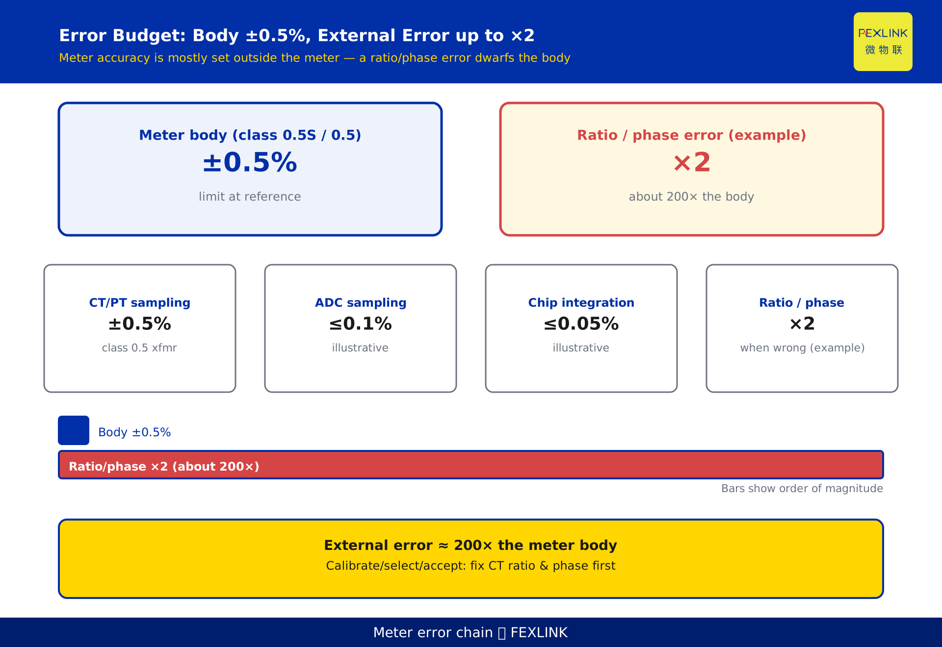
Put the four rings side by side (all illustrative / typical magnitudes; actual values depend on GB/T 17215 and device measurement):
- CT/PT sampling: about ±0.5% (for a class 0.5 transformer)
- ADC synchronous sampling: illustratively ≤0.1%
- Metering-chip integration: illustratively ≤0.05%
- Ratio / wiring phase: when wrong, off by a factor of two (×2, about +100%, constructed example)
The conclusion is clear: the meter body and transformer sit at the "fractions of a percent" scale; a wrong ratio or wiring sits at the "hundreds of percent" scale — roughly 200 times (×200) the meter body's accuracy. So the honest answer to "how can a meter reach 0.5-class accuracy" is not "the meter is precise," but "the links outside the meter are kept under control."
7. Three external stages where site error creeps in
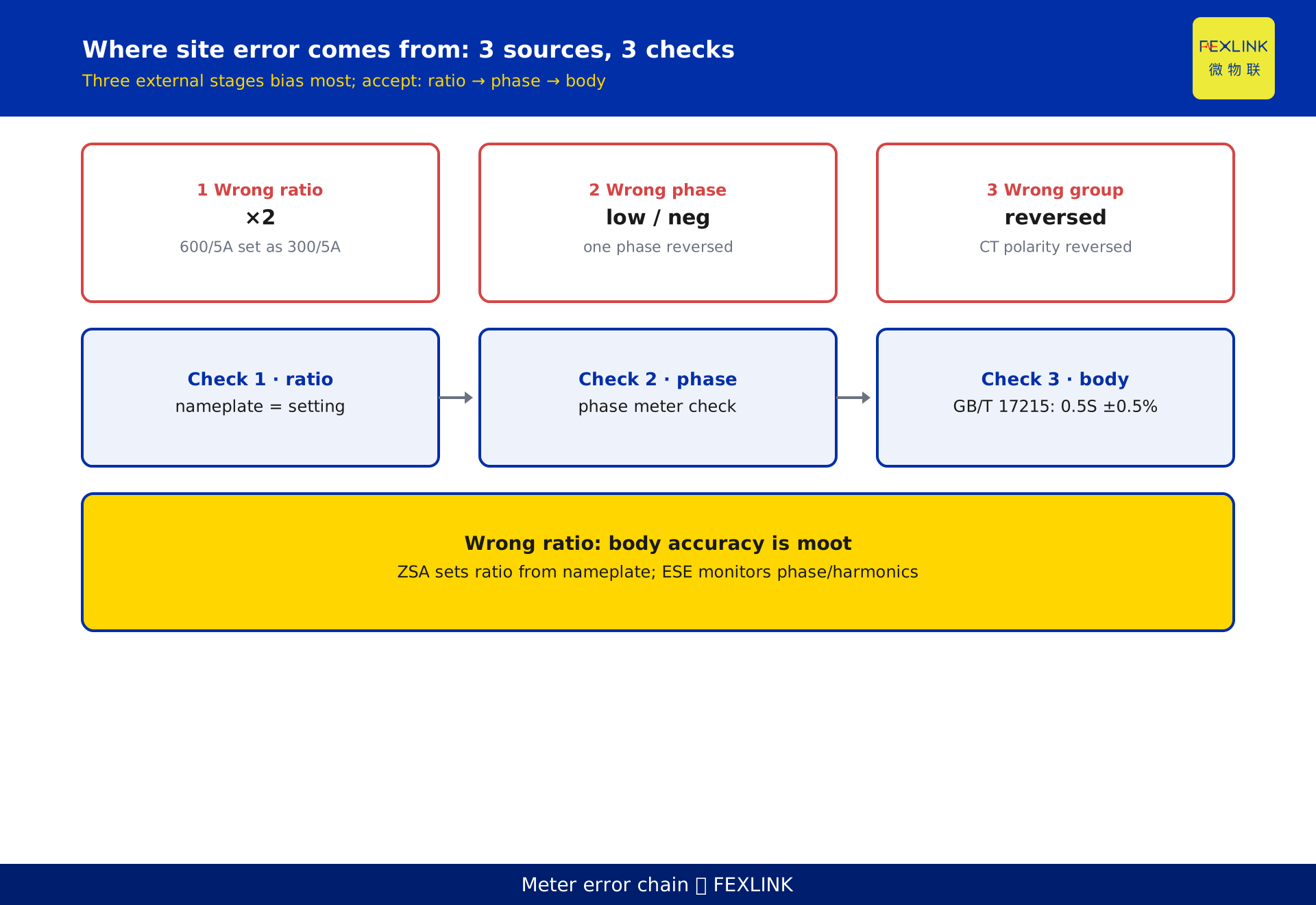
On real sites, the places that bias the energy most are not the meter body but these three:
- Wrong ratio. Actual CT 600/5A, but the meter set to 300/5A — half the ratio, reading about half the truth.
- Wrong phase sequence. One phase reversed or the phase order wrong, the power algebraic sum goes wrong: at best a low reading, at worst negative power or no metering.
- Wrong wiring group / polarity. A reversed CT polarity flips the power direction too.
All three share a trait: they raise no alarm, quietly bending every conclusion downstream.
8. A desensitized scenario: wrong ratio, reading off by half
The following is constructed to illustrate the point and represents no real customer.
A campus substation has two 10 kV incomers, each with a 600/5A current transformer and a 10kV/100V voltage transformer, feeding a ZSA embedded multi-function smart meter for total energy metering. During commissioning, the technician set the meter's CT ratio to 60 (from another circuit's 300/5A nameplate) instead of the correct 120.
Result: with 1 million kWh actually used on the primary side, the backend read only about 0.5 million kWh — a roughly twofold (×2) gap. Monthly settlement, demand statistics, and performance scoring all ran on that halved number, until a nameplate check during an equipment replacement exposed the mismatch. After correcting to 120, readings returned to normal.
This shows: when the ratio hop is wrong, whether the meter body is 0.5S or class 2 makes almost no difference to the number the user sees.
9. Decision advice: keep the error outside the meter
For selection and acceptance, three executable criteria — not "it depends":
- Criterion 1 (ratio first): before commissioning or acceptance, physically verify the CT/PT nameplate against the meter setting; only if they match may you test the meter body. A wrong ratio makes the meter body's accuracy irrelevant.
- Criterion 2 (phase next): use a phase-sequence meter to verify wiring; three-phase voltage and current sequence and group are correct, with no reversal and no polarity error.
- Criterion 3 (body last): only after the first two are clean, run the GB/T 17215 body-accuracy test; a 0.5S unit is judged pass at ±0.5% basic error under reference conditions.
For deployment, the ZSA embedded multi-function smart meter lets you configure the CT/PT ratio from the field transformer nameplate and supports phase-sequence and polarity checks at wiring time. When voltage and current phase plus harmonics need to be seen together, pair it with the ESE power-quality monitor for finer on-site diagnosis.
FAQ
Q: A meter rated 0.5S — does that mean its energy reading is only ±0.5% off?
No. The 0.5S class only bounds the meter body under reference conditions. The real reading is also shaped by CT/PT, wiring, and ratio settings, whose errors often far exceed 0.5%. An accurate body does not mean an accurate chain.
Q: Why do some sites insist on 0.5S rather than 0.5?
The 0.5S class extends the accuracy floor down to 1% of rated current, holding ±0.5% even at light, fluctuating loads; the 0.5 class relaxes at lower currents. Sites with deep night-time light load fit 0.5S better.
Q: How big an impact does a wrong CT ratio have?
If a real 600/5A is set as 300/5A, the ratio halves and the reading is off by about a factor of two (×2, constructed example only), far beyond the body's 0.5%. It is a different order of magnitude, not the same one.
Q: What happens if the phase sequence is reversed?
With one phase reversed or the sequence wrong, the power algebraic sum fails — at best a low reading, at worst negative power or no metering, usually with no alarm. Phase sequence and wiring group must be checked on site.
Q: At acceptance, check the meter first or the ratio first?
Check the ratio, phase sequence, and wiring group first, then test the meter body. A wrong ratio makes even a perfect body read wrong — get the order wrong and the test itself is meaningless.
Scope and limitations
- The error chain discussed here (CT/PT → ADC synchronous sampling → metering-chip integration → ratio conversion) applies to transformer-connected AC active energy meters; directly-connected meters have no transformer stage.
- The 0.5S/0.5/1/2 classes of GB/T 17215 are accuracy-class names given by the current standard; the statement that 0.5S holds ±0.5% from 1% to 120% of rated current is typical wording, and exact limits follow the standard text and verification regulations.
- The per-stage errors in section 6 are illustrative / typical magnitudes, given only to show magnitude distribution; actual values depend on the specific device and operating conditions and must follow GB/T 17215 and measurement. This article makes no concrete error promise.
- The campus scenario in section 8 is constructed to show ratio impact, is labelled a constructed example, and represents no real customer or project; actual ratios and reading deviations require the field nameplate and measurement.
- Functional descriptions of the ZSA embedded multi-function smart meter and the ESE power-quality monitor follow the latest selection manual and product knowledge base; this article is not a selection or procurement recommendation.
- Standard numbers cited are current as of writing; if a standard is revised, the quantitative conclusions here require rechecking.
Frequently Asked Questions
A meter rated 0.5S — does that mean its energy reading is only ±0.5% off?
No. The 0.5S class only bounds the meter body under reference conditions. The real reading is also shaped by CT/PT, wiring, and ratio settings, whose errors often far exceed 0.5%. An accurate body does not mean an accurate chain.
Why do some sites insist on 0.5S rather than 0.5?
The 0.5S class extends the accuracy floor down to 1% of rated current, holding ±0.5% even at light, fluctuating loads; the 0.5 class relaxes at lower currents. Sites with deep night-time light load fit 0.5S better.
How big an impact does a wrong CT ratio have?
If a real 600/5A is set as 300/5A, the ratio halves and the reading is off by about a factor of two (×2, constructed example only), far beyond the body's 0.5%. It is a different order of magnitude, not the same one.
What happens if the phase sequence is reversed?
With one phase reversed or the sequence wrong, the power algebraic sum fails — at best a low reading, at worst negative power or no metering, usually with no alarm. Phase sequence and wiring group must be checked on site.
At acceptance, check the meter first or the ratio first?
Check the ratio, phase sequence, and wiring group first, then test the meter body. A wrong ratio makes even a perfect body read wrong — get the order wrong and the test itself is meaningless.