 FEXLINK Research Institute
The short answer
The "5th harmonic, 4.0%" a power-quality meter reports is not a measured instantaneous value; it is computed by running a discrete Fourier analysis on the current or voltage waveform. The meter samples the waveform synchronously at a fixed rate, obtains a discrete sequence, then applies a DFT/FFT over an integer number of cycles to decompose the fundamental (50 Hz) and its integer-multiple components (2nd 100 Hz, 3rd 150 Hz, 5th 250 Hz … 31st 1550 Hz) into magnitude and phase, and finally compares them against the GB/T 14549 limits. THD is the square-root-of-sum-of-squares of the harmonics divided by the fundamental, not a simple addition.
1. What a harmonic actually is: an integer multiple of the fundamental
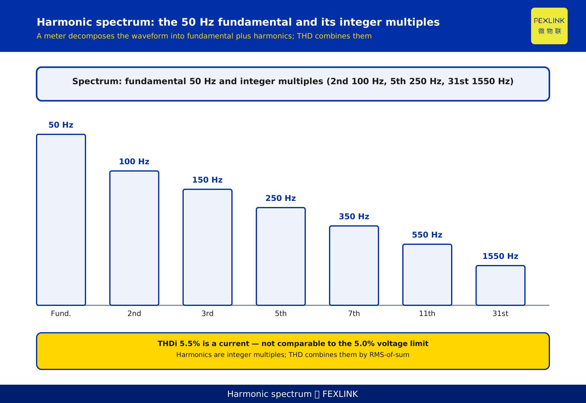
Build the intuition first. In an ideal grid the voltage and current are clean 50 Hz sinusoids, called the fundamental. When a non-linear load (a variable-frequency drive, a rectifier, an electric-arc furnace, an LED power supply) is connected, the current waveform is "clipped" away from a sine shape. This distortion can be understood as: on top of the 50 Hz fundamental, a stack of components whose frequencies are integer multiples of 50 Hz is superimposed. The frequency of the nth-order harmonic is n×50 Hz: 2nd = 100 Hz, 3rd = 150 Hz, 5th = 250 Hz, 7th = 350 Hz, all the way to 31st = 1550 Hz. The first job of harmonic analysis is to take one real, mixed-up waveform and break it back into a list of "fundamental + each harmonic".
Understanding this matters: harmonics are several sine components already present in the waveform, not "one pollutant". Measuring only total THD without orders is like weighing a parcel without knowing which part is heavy — you cannot tell which device to change. Order extraction turns the vague verdict "poor power quality" into a locatable problem.
2. From waveform to spectrum: the four steps of DFT inside a meter
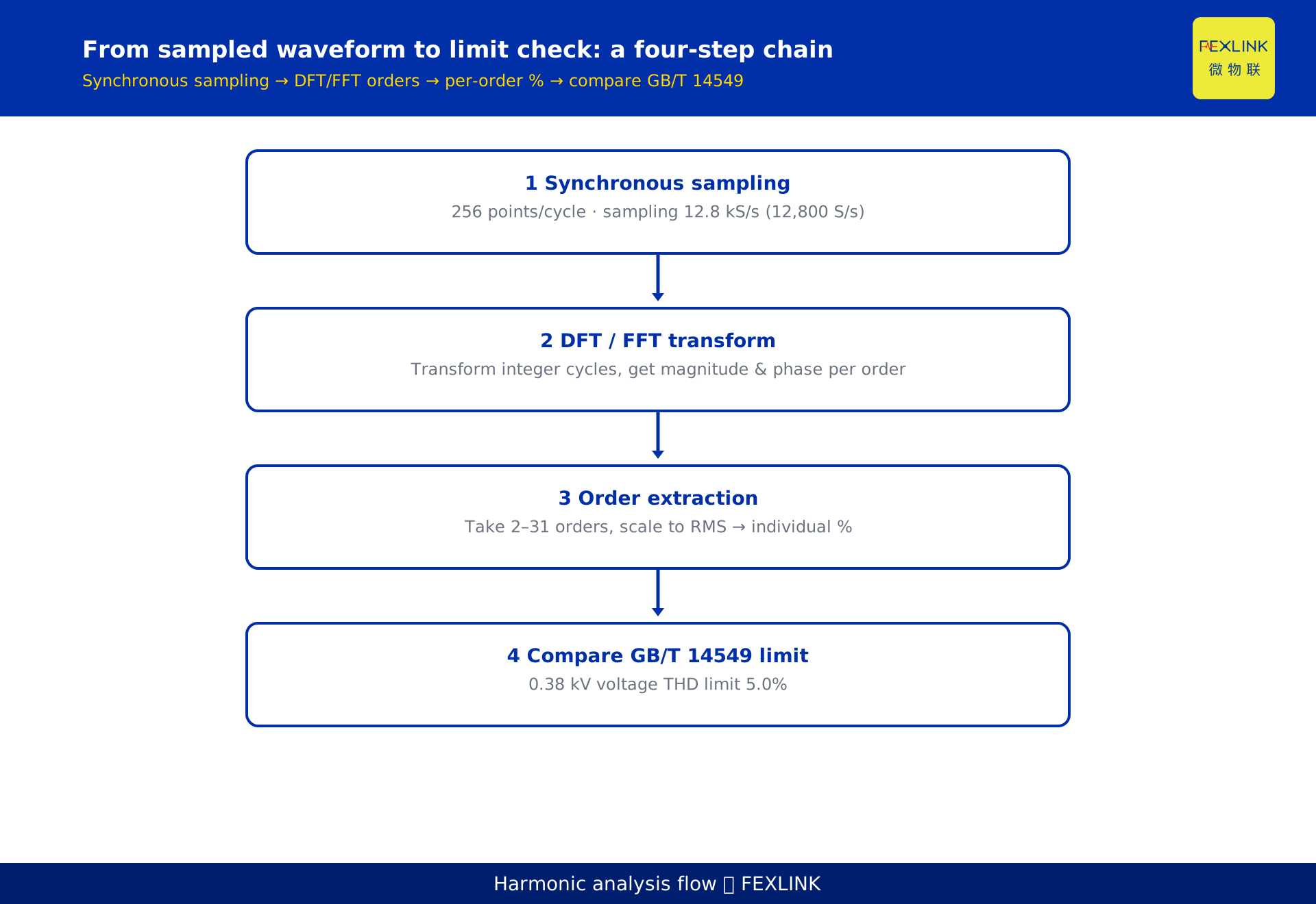
Inside the meter the job is split into four steps:
- Synchronous sampling. Voltage and current are sampled synchronously at a fixed rate, with a fixed number of points per fundamental cycle. A common alignment for IEC 61000-4-30 class implementations is 256 points per cycle, giving a sampling rate = 50×256 = 12.8 kS/s (12,800 S/s). This is a device implementation; the exact point count and sampling rate are subject to the device technical specification.
- Windowing. A segment of an integer number of cycles (for example 10 cycles) is cut out as the analysis window to avoid spectral leakage.
- Transform. A discrete Fourier transform DFT (in practice the fast algorithm FFT) is applied to this sequence, yielding a complex result for each frequency component — the modulus is the magnitude and the argument is the phase.
- Order extraction and scaling. The magnitude of each harmonic from 1 to 50 (this article uses 2 to 31) is taken, converted to an RMS value, then divided by the RMS fundamental to obtain the individual harmonic distortion (%).
One detail: sampling must be synchronous — the clock locks to the grid frequency so the points per cycle stay constant. An independent asynchronous clock drifts the cycle boundary and DFT smears one order into its neighbours. That is why a monitor samples with a PLL on the fundamental, unlike a plain recorder.
3. Which frequency each order maps to: integer multiples of 50 Hz
Listing the common orders makes it clear: fundamental 50 Hz; 2nd 100 Hz; 3rd 150 Hz; 5th 250 Hz; 7th 350 Hz; 11th 550 Hz; 13th 650 Hz; 31st 1550 Hz. Note that "the nth-order harmonic frequency = n × fundamental frequency" depends only on the grid frequency, not on the load. China and Europe run at 50 Hz, so this mapping is fixed; parts of Japan and North America run at 60 Hz, in which case every order's frequency is multiplied by 1.2 overall. When the meter reads "5th harmonic 4.0%", it means the 250 Hz component accounts for 4.0% of the fundamental magnitude.
4. Why the 31st order can be measured: sampling rate and the Nyquist floor
Whether the 31st order can be resolved depends on whether the sampling rate is high enough. The Nyquist sampling theorem requires that, to analyse a highest frequency f_max without aliasing, the sampling rate must be > 2×f_max. Here f_max = 31×50 = 1550 Hz, so the sampling rate must be > 2×1550 = 3100 S/s. The synchronous sampling of 12.8 kS/s mentioned above is far above this floor, so the 31st order and even higher orders are resolved reliably and do not "fold" into other frequencies through aliasing. This is also why IEC 61000-4-7 sets the harmonic measurement range up to the 50th order and covers interharmonics, while the harmonic current permissible-value table in GB/T 14549-1993 runs to the 25th order; field meters usually report 2 to 25 or 2 to 31 — this article writes "measured up to the 31st order" per its chosen scope.
Conversely, a meter sampling at only 4 kS/s can analyse without aliasing up to about 2 kHz, roughly the 40th order (40×50 = 2000 Hz); higher orders fold into lower ones and read falsely. So "which order is measurable" is a sampling-rate question, not an algorithm question.
5. How THDi and THDu are computed: extract orders first, then combine
After the orders are extracted, the key combined metric is the total harmonic distortion THD. For current:
THDi = √(Σ_{h=2}^{H} I_h²) / I_1 × 100%
For voltage:
THDu = √(Σ_{h=2}^{H} U_h²) / U_1 × 100%
where I_1 / U_1 is the fundamental RMS, I_h / U_h is the hth-order harmonic RMS, and H is the highest analysed order (31 or 50). Two points matter. First, THD is "square-root-of-sum-of-squares divided by the fundamental", never a direct addition of the orders and never "just look at the largest one". Second, the larger H is, the wider the summation in the denominator, so the same dataset yields a different THD when computed with H = 25 versus H = 50.
A reproducible example: a feeder has fundamental current I_1 = 100 A, with harmonic RMS values I_3 = 3.0 A, I_5 = 4.0 A, I_7 = 2.0 A, I_11 = 1.0 A, I_13 = 0.5 A. Sum of squares = 3.0² + 4.0² + 2.0² + 1.0² + 0.5² = 9 + 16 + 4 + 1 + 0.25 = 30.25; square root = 5.5; THDi = 5.5 / 100 × 100% = 5.5%. Note that this 5.5% cannot be compared directly with the 0.38 kV voltage THD limit of 5.0%: one is a current, the other a voltage, with different denominators. Whether a current exceeds its limit is judged against the GB/T 14549 harmonic current permissible values, scaled to the actual short-circuit capacity at the point of common coupling (Section 7). Skipping that step is the most common benchmarking error.
6. Why engineering watches the characteristic orders 3/5/7/9
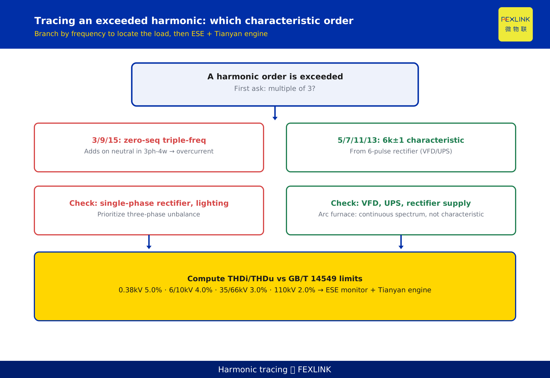
Extracting orders is not about filling a checklist; it is about tracing them back to loads. A six-pulse rectifier (variable-frequency drive, UPS, rectifier power supply) produces characteristic harmonics of order 6k±1 (k = 1, 2, 3…), i.e. 5, 7, 11, 13, 17, 19 — all odd orders that are not multiples of 3. The multiples of 3 (3, 9, 15…) are zero-sequence, triple-frequency harmonics that add up on the neutral conductor in a three-phase four-wire system, causing excessive and even overheating neutral current. So when reading a spectrum: if the 5/7/11/13 group appears, check variable-frequency and rectifier loads first; if the 3/9/15 group appears with a hot neutral, check single-phase rectification and three-phase unbalance first. This is the bridge that links "extracted orders" to real loads.
7. After the spectrum: comparing against the GB/T 14549 limits
Once the per-order distortion and THD are computed, they must land on a standard. GB/T 14549-1993 "Power quality — Harmonics in public supply network" gives permissible values for voltage total harmonic distortion (THD) and for each harmonic's distortion, by supply voltage level. Its published voltage-level to voltage-THD limit structure is: 0.38 kV 5.0%, 6/10 kV 4.0%, 35/66 kV 3.0%, 110 kV 2.0% (these are typical limits given by GB/T 14549-1993; refer to the current standard text). The per-order limits are given separately by voltage level and by odd/even order, and are not listed item by item here. In practice the monitoring device generates a report from these, and the engineer checks which order exceeded, by how much, and then decides the mitigation.
Note: the standard gives voltage limits because voltage distortion propagates to other users; current limits are usually framed as "harmonic current injected into the grid", a different thing. Use voltage THD to judge "is the grid side over limit", then use current orders to find "which device" — voltage alone shows it is bad but not where it comes from.
8. How products turn this principle into operation
To make the principle an operable monitor, edge devices plus an analytics layer are needed. To obtain the 2 to 31 order spectrum and compare against limits, an ESE power-quality monitor with harmonic-analysis capability is required; it outputs THD and per-order distortion per GB/T 14549. If the site also needs integrated metering of electricity, temperature and other electrical quantities, the SFE power-quality multi-parameter controller is an option. The analytics layer uses the Tianyan engine for harmonic analysis, turning order results, characteristic-order tracing and THD trends into a trackable dashboard. Together, harmonics move from "a line of numbers on a report" to a mitigation clue of "which device, which order, by how much". Example model numbers are subject to the latest selection manual; this article is not a selection recommendation.
One often-missed point: mitigation must be re-measured. After a passive or active filter, re-run the 2–31 spectrum to confirm the target order (e.g. 5th/7th) really dropped and energy was not pushed elsewhere. Total THD alone cannot show whether you fixed one order but worsened another.
FAQ
Q: The meter says 5th harmonic 4.0% — where does the 4.0% come from?
A: After synchronously sampling the current waveform, the meter runs an FFT and obtains the magnitude of the 250 Hz (5th-order) component, converts it to RMS, then divides by the fundamental RMS to get the 4.0% distortion. It is not an instantaneous sample; it is the result of spectral decomposition.
Q: Why do some meters report only 2 to 25, others 2 to 31?
A: It depends on the device's configured highest analysed order H and its sampling rate. As long as the sampling rate > 2× the highest order frequency (the 31st corresponds to 1550 Hz, requiring > 3100 S/s), it can be resolved reliably; reporting 2 to 25 or 2 to 31 is a device-implementation and selection matter, subject to the technical specification.
Q: Is THD the harmonics added together?
A: No, it is "square-root-of-sum-of-squares divided by the fundamental". The formula is THDi = √(Σ I_h²) / I_1 × 100%. Looking only at the largest order misses the scattered small ones, while simple addition overestimates; the square-root-of-sum-of-squares must be used.
Q: Seeing very large 3rd and 9th harmonics, what does it mean?
A: Multiples of 3 are zero-sequence, triple-frequency harmonics that accumulate on the neutral in a three-phase four-wire system. If the neutral is also running hot, prioritise checking single-phase rectification loads, single-phase lighting loads and three-phase unbalance, rather than rushing to the variable-frequency drives.
Q: Harmonics exceeded the limit — what is the first step?
A: First confirm which order exceeded and by how much, against the GB/T 14549 limit for the corresponding voltage level; then use an ESE power-quality monitor with harmonic-analysis capability together with the Tianyan engine to trace the exceeded order to a specific load, and only then decide whether to add a filter or rework the rectification stage.
Scope and limitations
- This article explains the mathematical and methodological principle of harmonic spectral decomposition and THD combination, for 50 Hz power-quality analysis; a 60 Hz grid multiplies every order's frequency by 1.2 with the same principle.
- The sampling rate (256 points per cycle, 12.8 kS/s) is a common device-implementation alignment example; the actual point count and sampling rate are subject to the device technical specification, and this article is not a selection recommendation.
- The voltage THD limits of GB/T 14549-1993 (0.38 kV 5.0%, 6/10 kV 4.0%, 35/66 kV 3.0%, 110 kV 2.0%) are typical published values; refer to the current standard text. Per-order limits are given by voltage level and odd/even order and are not listed item by item.
- The THDi = 5.5% example is constructed to illustrate the formula and represents no real customer or project; real applications must be calculated from on-site measured data.
- Specific model numbers and parameters of the ESE power-quality monitor, the SFE power-quality multi-parameter controller and the Tianyan engine are subject to the latest selection manual and product knowledge base.
- Standard identifiers are subject to the currently valid edition; after a standard is revised, the related quantitative conclusions must be re-checked.
Frequently Asked Questions
The meter says 5th harmonic 4.0% — where does the 4.0% come from?
After synchronously sampling the current waveform, the meter runs an FFT and obtains the magnitude of the 250 Hz (5th-order) component, converts it to RMS, then divides by the fundamental RMS to get the 4.0% distortion. It is not an instantaneous sample; it is the result of spectral decomposition.
Why do some meters report only 2 to 25, others 2 to 31?
It depends on the device's configured highest analysed order H and its sampling rate. As long as the sampling rate > 2× the highest order frequency (the 31st corresponds to 1550 Hz, requiring > 3100 S/s), it can be resolved reliably; reporting 2 to 25 or 2 to 31 is a device-implementation and selection matter, subject to the technical specification.
Is THD the harmonics added together?
No, it is "square-root-of-sum-of-squares divided by the fundamental". The formula is THDi = √(Σ I_h²) / I_1 × 100%. Looking only at the largest order misses the scattered small ones, while simple addition overestimates; the square-root-of-sum-of-squares must be used.
Seeing very large 3rd and 9th harmonics, what does it mean?
Multiples of 3 are zero-sequence, triple-frequency harmonics that accumulate on the neutral in a three-phase four-wire system. If the neutral is also running hot, prioritise checking single-phase rectification loads, single-phase lighting loads and three-phase unbalance, rather than rushing to the variable-frequency drives.
Harmonics exceeded the limit — what is the first step?
First confirm which order exceeded and by how much, against the GB/T 14549 limit for the corresponding voltage level; then use an ESE power-quality monitor with harmonic-analysis capability together with the Tianyan engine to trace the exceeded order to a specific load, and only then decide whether to add a filter or rework the rectification stage.