 FEXLINK Research Institute
The short answer
When a plant's main meter reads 100,000 kWh for a month but all submeters add up to only 90,000 kWh, the 10,000 kWh gap (10%) is rarely true line loss. In most cases it is a metering mismatch: a wrong multiplier or ratio setting, a circuit that was never metered, a current transformer poorly matched to load, or a communication outage that dropped data. The right move is to rule out pseudo-loss before talking about real loss. Work the five steps in order of cost, cheapest first: check multiplier and ratio settings, find unmetered circuits, verify CT-to-load matching, recover missing communication periods, and only then calculate genuine line loss. Most 10% gaps trace to a multiplier error or a missing submeter, not to the wires.
A worked example: who is lying about 10,000 kWh
The figures below are constructed to illustrate the method and do not represent any real customer or project.
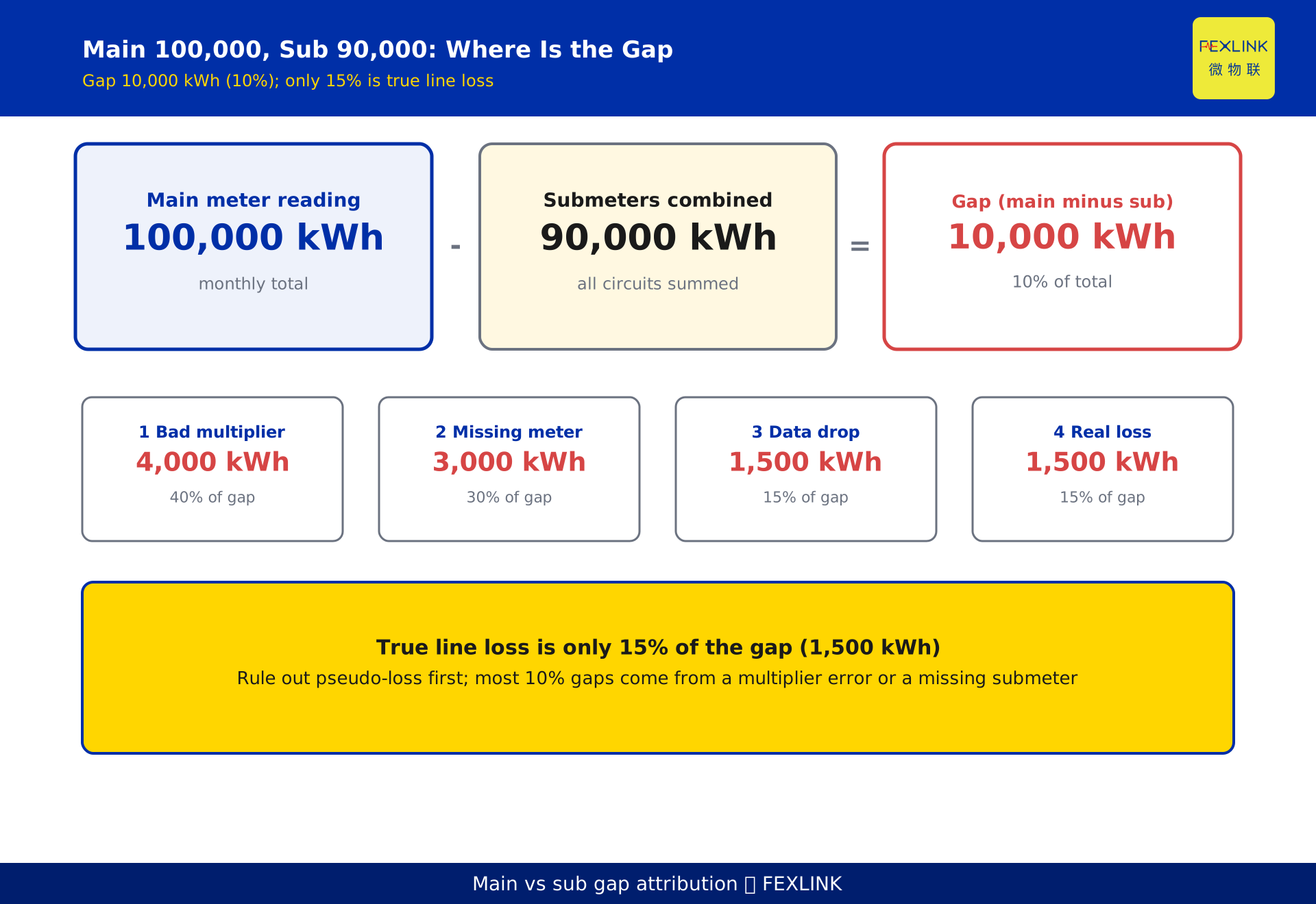
A park has one 10 kV incoming line. The main meter reads 100,000 kWh in a month. A dozen submeters on individual circuits read a combined 90,000 kWh. The main-minus-sub gap is 10,000 kWh, or 10% of total consumption.
In an energy-review meeting that 10% was reported straight onto the slide as "line-loss rate 10%". The problem: genuine low-voltage distribution losses are normally in the single-digit percentage range, so 10% is already suspiciously high. More importantly, that number conflates "metering not aligned" with "wires actually leaking", so every later fix misses the target.
Split the 10,000 kWh gap and the causes rarely stand alone:
- Wrong multiplier or ratio settings create a fixed proportional bias, about 40% of the gap, or 4,000 kWh;
- A circuit with no submeter, a systematic omission, about 30% of the gap, or 3,000 kWh;
- A communication outage that dropped some periods, about 15% of the gap, or 1,500 kWh;
- Genuine line loss, about 15% of the gap, or 1,500 kWh.
Notice that the electricity truly lost on the wires may be only a small slice of the gap. Separate it from the metering problems first, or the remediation direction drifts.
Two kinds of loss: real and pseudo
The first step in judging whether a loss rate is normal is to separate real loss from pseudo-loss.
Real line loss is energy physically dissipated: conductor resistance heating (copper loss), transformer core excitation (iron loss), and extra loss from reactive current. In a normal low-voltage network this sits in the single-digit percentage range, typically 2% to 8% by engineering experience. Anything well above that range deserves suspicion.
Pseudo-loss is not electricity leaking; it is the books being incomplete or wrong. It changes only the number you see. A wrong multiplier shifts every reading by a fixed proportion. An unmetered circuit simply never enters the books. A communication drop makes a period vanish. A CT matched poorly to load under-reads at small loads. Pseudo-loss also shows up as a "main-minus-sub" gap, but its root cause is metering, not the line.
One-line test: align the metering basis first; whatever gap remains may be real loss. Any loss rate reported before alignment is essentially contaminated by pseudo-loss.
Five steps, cheapest first
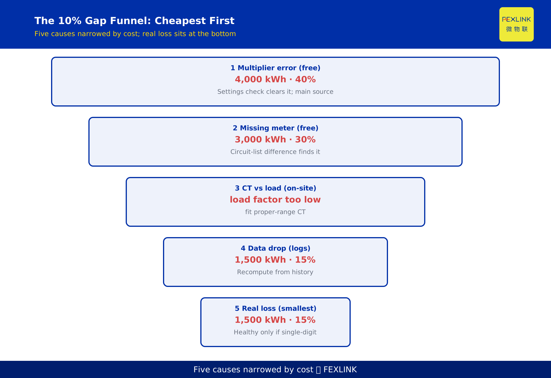
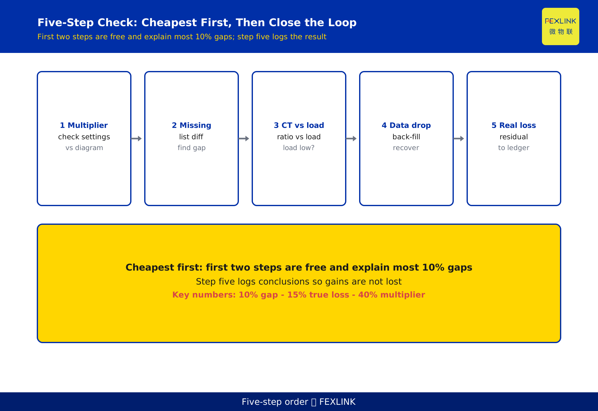
Troubleshooting is not random shooting. Order it by cost, from configuration errors to physical hardware loss. The early steps are nearly free: just checking settings and listing circuits. Later steps touch equipment and need measurement. The order itself saves time and money.
The five steps:
- Check the multiplier and ratio settings on the main meter and every submeter;
- Find any circuit that was never fitted with a submeter;
- Verify the current-transformer ratio matches the actual load;
- Reconcile communication gaps and recover the dropped energy;
- Compute genuine line loss and close the loop into the ledger.
The incremental value of this order: the first two steps explain most 10%-scale gaps and cost nothing. Many teams jump straight to suspecting the line and schedule patrols, only to find the line is fine and the money is spent for nothing. Do the first two steps and the gap often disappears.
Step 1: are the multiplier and ratio settings correct
Multiplier and ratio are the most overlooked and the most damaging settings in metering. A current transformer (CT) shrinks a large current to a small one for the meter, and that shrinkage factor must appear both in the wiring and in the data system's parameter settings. If the in-meter multiplier is wrong, or the main uses one ratio while a sub uses another, every reading shifts by a fixed proportion. That is the fixed bias described above.
The dangerous part is that it never alarms. A wrong multiplier pushes all data steadily in one direction; the system sees a "smooth, seemingly normal" series and raises no flag. It quietly biases every conclusion afterward. After any handover, retrofit, or capacity expansion, re-verify the ratio, phase sequence, and wiring group, and keep a record.
The test is simple: walk the main and every submeter against the original wiring diagram, line by line, through multiplier, CT ratio, and PT ratio. The theoretical main reading should reconcile with the submeter sum under the same basis. Whatever will not reconcile, book it to the multiplier/ratio account.
Step 2: is any circuit missing a submeter
A missing submeter is another common source of pseudo-loss. When a park adds a production line, installs equipment, or changes layout, the metering may not expand with it; that energy then appears only on the main meter, with no corresponding entry on the submeter side.
To locate a missing circuit, use the circuit list, not the meters. List every branch under the main incoming line and take the set difference against the list of circuits that actually have submeters. Any place that consumes power but has no submeter is a source of the gap. These omissions often cluster around later-added air-conditioning rooms, charging piles, dormitory blocks, or temporary taps.
Finishing this step alone recovers a large part of most 10% gaps, and it costs nothing: it is an inventory exercise.
Step 3: does the CT ratio match the load
Even with the ratio set correctly, a poorly chosen CT under-reads systematically. A current transformer has a comfortable range; when the actual load stays far below its rated primary current, say below 30% of rating for long stretches, accuracy degrades and readings drop. In other words, the circuit is drawing power but the meter "cannot weigh it accurately".
The test is the load factor: for a typical period, compare the circuit current against the CT rated primary current. If it sits low persistently, fit a CT of a more suitable range or merge small-load circuits. This step needs on-site measurement and costs more than the first two, but it is the last check that clears the "inaccurate metering" category, and only after it can you trust a real-loss analysis.
Step 4: how much did the communication gaps eat
Modern metering relies on a gateway pulling meter data on a cycle. The moment the gateway loses contact with a meter, that period's energy never enters the books, and by the time contact returns the gap already exists. The signature of communication loss is distinctive: it drops data in whole contiguous blocks rather than shaving a little off everywhere.
The test is data completeness. With a collection device such as the ESX edge computing gateway, you can check each meter's online rate and data back-fill records. Recompute the missing periods from that circuit's historical average load for the same period, and you can quantify this part of the gap. Bringing communication quality into daily monitoring beats troubleshooting it after the fact.
Step 5: compute real loss and close the ledger
Once the first four steps have largely cleared pseudo-loss, whatever remains is real loss. Now the residual of "main minus sub" is a credible line-loss rate. If the residual falls back into the single-digit range, the system is healthy; if it stays high, then schedule line patrols, check contact resistance, and add reactive compensation as hardware fixes.
The key is closing the loop. Every conclusion from a round of checks, whether the multiplier was corrected, the missing circuit metered, the CT replaced, or the data recovered, goes into the metering ledger with a version and a date. Otherwise the next capacity expansion or handover brings the same gap back in a new face. The ledger loop is the only way to stop this round's gains from leaking away.
How this differs from KD-0464
The neighboring article KD-0464 covers the small bias caused by multiplier truncation: a predictable, small, systematic offset whose principle is clear and whose impact is controllable. This article is not about that gentle small bias; it is about an on-site loss investigation at the 10% scale, where the root cause is usually a structural issue such as a multiplier error or a missing submeter, different in both magnitude and treatment.
The incremental contribution here is making the five-step order explicit: from a zero-cost multiplier/ratio check, to a circuit census, then CT matching and communication recovery, and only lastly real loss. This "cheapest first" order is the first principle for handling a large-scale on-site loss, and it is the essential distinction from the small-bias principle in KD-0464.
Putting it on the ground: the right tools
Investigation needs data to land. Circuit-level metering uses the ESA full-element smart meter (for example ESA-22131-R, 3×220/380V, RS485 Modbus), fitted per circuit and read on a cycle, which answers "which line is the deviation on". Data aggregation and back-fill are handled by the ESX edge computing gateway, which pulls each meter's data and records the missing periods when communication drops. Up top, the digital electrical intelligent supervision system unifies the main meter, submeters, multipliers, ratios, and circuit list, so the "main-minus-sub" gap can be decomposed with one click into four buckets: multiplier, missing circuit, dropped data, and real loss.
The value of tooling is not to think the conclusion for you, but to turn troubleshooting from guesswork into a data exercise. The first two zero-cost checks become far more efficient once a complete circuit list and multiplier ledger are in place.
FAQ
Q: Does a 10% gap automatically mean the line is leaking?
Not necessarily. In most 10% cases the root cause is a metering issue such as a wrong multiplier or a missing submeter, and the electricity truly lost on the wires is often only a small part. The correct order is to rule out pseudo-loss before discussing real loss.
Q: Why does a wrong multiplier never trigger an alarm?
Because a wrong multiplier pushes all data steadily in one direction, and the system sees a smooth, seemingly normal series that raises no exception. It quietly biases every later conclusion, so the only defense is manually checking each meter's ratio and settings.
Q: How do I tell whether a circuit is missing a submeter?
Do not look at the meters; look at the circuit list. List every branch under the main incoming line and take the set difference against circuits that have submeters. Any powered place without a submeter is a gap source. Later-added air-conditioning rooms, charging piles, and dormitory blocks are the usual culprits.
Q: What happens if the CT ratio does not match the load?
When the actual load stays far below the CT rated primary current, accuracy degrades and readings under-read systematically; the circuit draws power but the meter cannot weigh it accurately. The test is the load factor, and a persistently low one calls for a CT of a more suitable range.
Q: Can the energy dropped during a communication outage be recovered?
Yes, but only with records. Check each meter's online rate and data back-fill log, then recompute the missing periods from that circuit's historical average load for the same period to quantify the gap. Bringing communication quality into daily monitoring is cheaper than troubleshooting it afterward.
Scope and limitations
- The method for investigating a main-minus-sub gap applies to commercial and industrial distribution systems that use a main meter plus submeters, or a main incoming line plus branch-circuit metering. Single-metering users cannot use the submeter comparison logic.
- The statements that normal low-voltage line loss sits in the single-digit percentage range and that most 10% gaps come from multiplier errors or missing submeters are engineering experience and methodological framing; actual thresholds vary with system scale, line length, and load profile, and should follow current standards and on-site measurement.
- Any metering basis involving current-transformer ratios, multiplier settings, or load-factor criteria, where specific accuracy classes or precision coefficients apply, follows current standards and equipment nameplates; this article gives no specific coefficients.
- The example parameters in this article are constructed to illustrate the problem and do not represent any real customer or project; actual gap decomposition and loss-rate accounting must be based on site survey and measured data.
- The specific models and parameters of the associated products ESA full-element smart meter, ESX edge computing gateway, and digital electrical intelligent supervision system follow the latest selection manuals and product documentation; this article is not a selection or procurement recommendation.
Frequently Asked Questions
Does a 10% gap automatically mean the line is leaking?
Not necessarily. In most 10% cases the root cause is a metering issue such as a wrong multiplier or a missing submeter, and the electricity truly lost on the wires is often only a small part. The correct order is to rule out pseudo-loss before discussing real loss.
Why does a wrong multiplier never trigger an alarm?
Because a wrong multiplier pushes all data steadily in one direction, and the system sees a smooth, seemingly normal series that raises no exception. It quietly biases every later conclusion, so the only defense is manually checking each meter's ratio and settings.
How do I tell whether a circuit is missing a submeter?
Do not look at the meters; look at the circuit list. List every branch under the main incoming line and take the set difference against circuits that have submeters. Any powered place without a submeter is a gap source. Later-added air-conditioning rooms, charging piles, and dormitory blocks are the usual culprits.
What happens if the CT ratio does not match the load?
When the actual load stays far below the CT rated primary current, accuracy degrades and readings under-read systematically; the circuit draws power but the meter cannot weigh it accurately. The test is the load factor, and a persistently low one calls for a CT of a more suitable range.
Can the energy dropped during a communication outage be recovered?
Yes, but only with records. Check each meter's online rate and data back-fill log, then recompute the missing periods from that circuit's historical average load for the same period to quantify the gap. Bringing communication quality into daily monitoring is cheaper than troubleshooting it afterward.