 FEXLINK Research Institute
The short answer
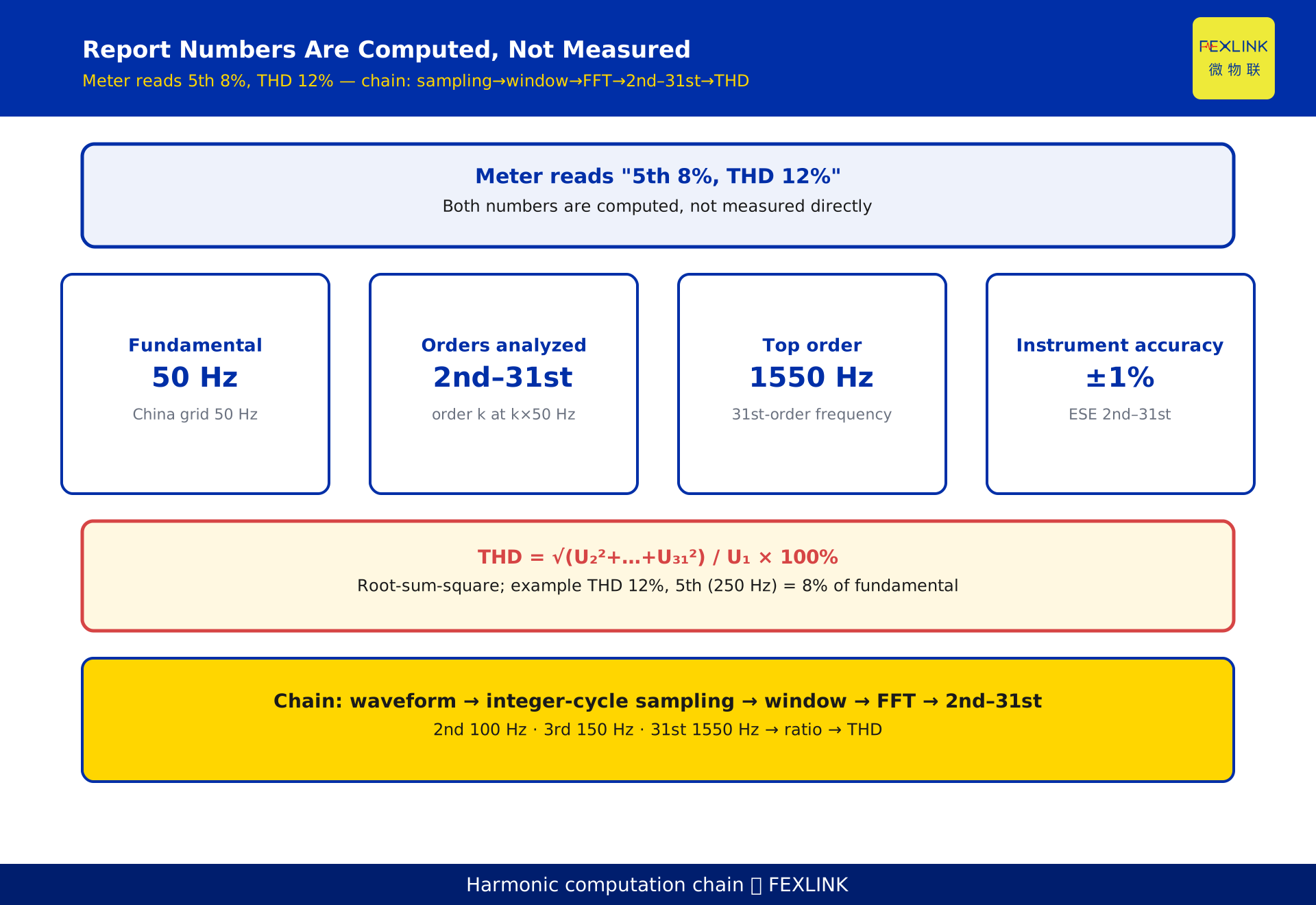
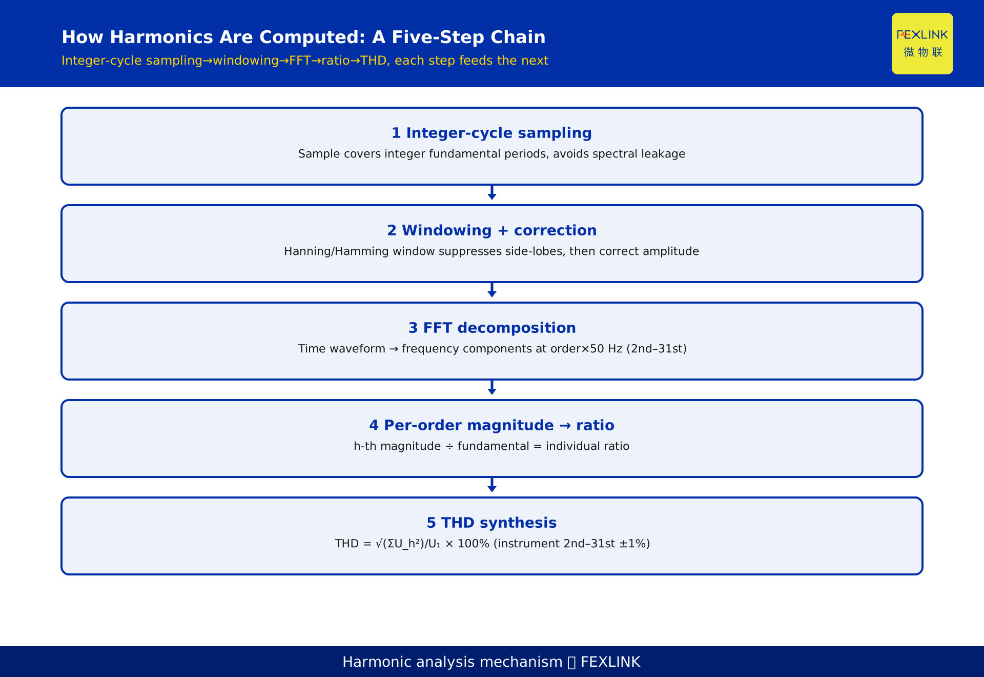
The "5th harmonic 8%, THD 12%" on a power-quality report is not a direct meter reading; it is the end of a computation chain: integer-cycle sampling, windowing with correction, an FFT splitting the signal into the fundamental and the 2nd through 31st components, a per-order ratio for each, and a root-sum-square combination into THD. The meter captures time-domain samples of voltage and current; order numbers, ratios and distortion figures are derived afterwards. Before comparing data with any limit, check the chain: was sampling integer-cycle, was the window corrected, is the stated accuracy adequate, and is the THD denominator consistent? On a 50 Hz network the h-th harmonic sits at h x 50 Hz, so the 2nd is 100 Hz, the 3rd is 150 Hz, the 5th is 250 Hz and the 31st is 1550 Hz. Only then do report percentages become reproducible numbers.
1. Ask the right question first: measured or computed?
A report usually shows individual harmonic ratios and THD. The better first question is not whether a limit is exceeded but where those numbers came from. Analog-to-digital conversion yields time-domain samples, and no sample contains a field called "5th harmonic 8%". The 5th order is the amplitude share of the 250 Hz bin after frequency decomposition; THD is the square root of the sum of squares of the per-order ratios. Both are computed, not sensed.
That distinction matters. Error in a measured quantity comes from the sensor and its range; error in a computed quantity accumulates along the chain. A misaligned window, a missing correction or a different denominator produces different numbers from the same waveform. When one order jumps between two measurements, suspect the first three links before the load. This article follows three gates, two metrics and one register: integer-cycle sampling, window correction and FFT; the individual ratio and THD; and a written check register.
2. Gate one: integer-cycle sampling and spectral leakage
FFT assumes the analysed segment joins end to end and repeats within the window. If the window does not cover an integer number of fundamental cycles, the edges are discontinuous and FFT spreads energy from one frequency across its neighbours: spectral leakage. One order reads low, its neighbours read high, and the result shifts when the sampling start point moves.
The remedy is integer-cycle sampling, with sampling rate and samples per cycle chosen against the fundamental, plus synchronous sampling or frequency tracking when the grid drifts. The test is plain: repeat under the same steady condition; stable per-order amplitudes with no irregular see-saw between adjacent orders mean this gate probably passed, while drift with the start point points to synchronisation. Aligning the window does not remove every leak: finite record length and interharmonics still push energy into nearby bins, which the next gate handles.
3. Gate two: windowing and window correction
FFT on a finite record is equivalent to a rectangular window, whose high sidelobes leak badly. A lower-sidelobe window such as Hann or Hamming makes energy outside the main lobe decay quickly, but it also reduces amplitude inside the main lobe. Without restoration, every individual ratio reads systematically low.
Window correction applies an amplitude recovery factor for the chosen window. Windowing and correction are one paired action; doing only the first half adds a fresh bias. This is deceptive: a report without correction appears to show less harmonic content and can be misread as good power quality. The test must be a pair - was a window applied, and was the correction factor matched to it? Together with integer-cycle sampling these are the first two gates of trustworthiness. Both belong to the measurement stage and are independent of the THD denominator chosen later.
4. Gate three: FFT and the 2nd through 31st orders
FFT converts time-domain samples into frequency-domain components, each with frequency and amplitude. On a 50 Hz network the h-th harmonic is h x 50 Hz: the 2nd is 100 Hz, the 3rd is 150 Hz, the 5th is 250 Hz, through to the 31st at 1550 Hz. Instruments commonly report the 2nd to 31st orders, a range set by the applicable standard plus instrument bandwidth and algorithms. This article lists no upper order and no limit table; the current standard text and the instrument specification govern.
"5th 8%" is the 250 Hz bin relative to the fundamental. The order also hints at the load: six-pulse conversion concentrates around the 5th and 7th, while integer multiples of 3 behave differently in three-phase systems (section 6). Identify which order is elevated before inferring the load; that beats staring at a single THD total. Where interharmonics or fast-fluctuating loads exist, an integer-order spectrum may be incomplete and should be combined with recorded waveforms.
5. Two metrics: the individual ratio and the THD denominator
The individual ratio and THD are both ratios but divide by different things. The ratio is one harmonic amplitude over the fundamental; THD is the root-sum-square of harmonics over a denominator. One numerator is a single term, the other a square root of squares, so THD is not the sum of the individual ratios.
The denominator is the crux. Using the fundamental amplitude and using total RMS are two definitions; the same waveform yields two THD figures, both arithmetically correct yet unequal. Without a stated denominator, numbers across instruments are not comparable, so check the denominator first, then the measurement stage, then the load. Constructed example: with only the 5th at 8% and the 7th at 4%, root-sum-square gives the square root of (8 squared plus 4 squared), that is the square root of 80, about 8.9%, not a simple sum. If the report also states THD 12%, other ignored orders or a different denominator may explain it. This illustrates the algorithm only.
6. Why the 3rd harmonic is special in three-phase systems
The 3rd order and its integer multiples (3, 9, 15 and so on) are zero-sequence harmonics: equal in magnitude and identical in phase across a balanced three-phase system. Because they are in phase, their vector sum does not cancel between phases - a point often stated backwards.
The consequence depends on wiring. In a three-phase four-wire system the neutral provides a path, so the 3rd harmonic currents add arithmetically in the neutral; neutral current can approach or exceed phase current while a phase ammeter reveals little, hence the overheating risk. In a three-phase three-wire system there is no neutral path, so zero-sequence current is absent from line currents; line voltage usually contains no 3rd harmonic even where phase voltage does. A three-phase survey therefore cannot take one phase or only line current. Actual neutral current depends on load and wiring; no fixed multiplier or limit is given here.
7. What a stated instrument accuracy of ±1% really means
Harmonic amplitudes are far smaller than the fundamental. Leakage from the first two gates and residual correction error land on amplitude accuracy. The ESE power-quality monitor states ±1% for the 2nd through 31st harmonics - a manufacturer-disclosed specification, not an industry threshold, and neither an evaluation nor a ranking of other products. The FSE power-quality controller passes such data upstream.
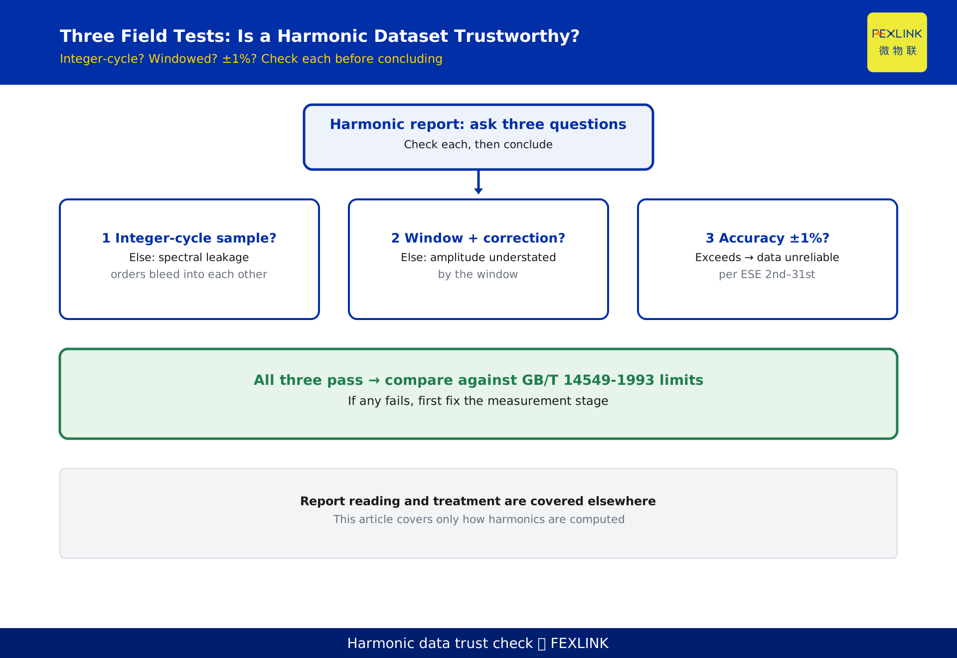
Read that figure with three things: the order range it covers, the conditions under which it holds, and whether the first two gates were done correctly. A stated accuracy is a capability under specified conditions; if sampling was not integer-cycle or the window was not corrected, the error is in the measurement stage and ±1% cannot vouch for the report. Conversely, limited accuracy alone is no reason to discard a report: confirm the three gates, check that the accuracy class covers the orders of interest, then compare with limits.
8. A constructed example: walking the whole chain
This scenario is constructed and represents no real customer or project. A factory report shows a 5th harmonic ratio of 8% and THD 12%, and the operator is stuck on whether a limit is exceeded. Along the chain: confirm the window covers an integer number of 50 Hz cycles; confirm a window with matching correction; FFT yields the 2nd to 31st orders with the 5th at 250 Hz largest at 8%; the per-order ratios combine into THD 12%.
The real issue lies outside the limit question: a single 5th at 8% cannot combine into 12%, so other orders contribute appreciably and the spectrum must be read order by order. The signature narrows suspicion toward six-pulse conversion loads; neutral current and three-phase balance then decide whether the 3rd and its multiples need attention. The M06 harmonic analysis module of the Taiyi intelligent control hub recomputes such chains into a harmonic fingerprint library. The point is the sequence: verify the measurement stage, then the convention, then the load. Skipping a step misreads a computation error as equipment failure.
9. Three field tests and a four-column register
Condense the above into a four-column written register: item and identifying information; the three measurement-stage tests; computation convention and order range; and conclusion with owner.
The tests are fixed. Was sampling integer-cycle? Non-integer-cycle sampling shows neighbouring orders bleeding and drifting with the start point. Was a window applied with matching correction? Windowing alone pushes individual ratios low. Does the stated accuracy for the 2nd through 31st orders cover the orders of interest, and is the denominator recorded? Only when all three pass are numbers suitable for comparison with limits in the current standard; if any fails, look in the measurement stage. Record observable facts: window start point, window and correction method, instrument model and accuracy marking, then a pass-or-recheck conclusion with an owner. Such a register survives shift changes and lets a new engineer recompute along the same chain.
FAQ
Q: What is the difference between an individual harmonic ratio and THD?
The ratio is one harmonic amplitude over the fundamental; THD is the root-sum-square of harmonics over a denominator. One numerator is a single term, the other a square root of squares; they cannot be equated.
Q: Why does one harmonic order jump between two measurements?
Usually sampling was not integer-cycle, or a window was applied without correction, causing leakage between neighbouring orders. Check the three tests in section 9 before discussing the load.
Q: Why does the 3rd harmonic need separate attention in three-phase systems?
The 3rd and its integer multiples are zero-sequence and in phase across the phases, so they do not cancel. In a four-wire system they add in the neutral, which can raise neutral current while a phase ammeter shows little.
Q: If the instrument states ±1%, is the reported 8% necessarily accurate?
Not necessarily. ±1% is a stated accuracy for the 2nd to 31st amplitudes under specified conditions, presuming correct sampling and window correction. A gap in the measurement stage is a different matter.
Q: If orders stop at the 31st, can higher orders be ignored?
The 2nd to 31st covers the main concerns of most distribution scenarios. Whether higher orders matter depends on the standard, instrument bandwidth and the load; this article sets no upper order.
Scope and limitations
- This article covers only the algorithm chain of how harmonics are computed: integer-cycle sampling, window correction, FFT, individual ratio and THD. How to read report numbers and how to treat harmonics are covered separately and are not expanded here.
- GB/T 14549-1993, "Power quality - Harmonics in public supply networks", is cited only as a named framework. Clauses, order ranges and limits follow the current valid edition; this article lists no limit table and quotes no clause numbers.
- The ±1% figure is a manufacturer-disclosed specification of the ESE power-quality monitor for the 2nd to 31st harmonics, not an evaluation or ranking of other products.
- The factory report in section 8 (5th at 8%, THD 12%) and the example in section 5 (8%, 4%, square root of 80 about 8.9%) are constructed, representing no real customer or measured data; field instruments govern actual readings.
- The frequency conversion (50 Hz fundamental, h-th harmonic at h x 50 Hz) and zero-sequence addition in the neutral are published circuit theory. Current magnitudes depend on wiring and load; no fixed multiplier is given here.
- This article does not cover interharmonics, flicker or transient events. Those need other analysis tools; an integer-order spectrum from the 2nd to the 31st is not a complete conclusion.
Frequently Asked Questions
What is the difference between an individual harmonic ratio and THD?
The ratio is one harmonic amplitude over the fundamental; THD is the root-sum-square of harmonics over a denominator. One numerator is a single term, the other a square root of squares; they cannot be equated.
Why does one harmonic order jump between two measurements?
Usually sampling was not integer-cycle, or a window was applied without correction, causing leakage between neighbouring orders. Check the three tests in section 9 before discussing the load.
Why does the 3rd harmonic need separate attention in three-phase systems?
The 3rd and its integer multiples are zero-sequence and in phase across the phases, so they do not cancel. In a four-wire system they add in the neutral, which can raise neutral current while a phase ammeter shows little.
If the instrument states ±1%, is the reported 8% necessarily accurate?
Not necessarily. ±1% is a stated accuracy for the 2nd to 31st amplitudes under specified conditions, presuming correct sampling and window correction. A gap in the measurement stage is a different matter.
If orders stop at the 31st, can higher orders be ignored?
The 2nd to 31st covers the main concerns of most distribution scenarios. Whether higher orders matter depends on the standard, instrument bandwidth and the load; this article sets no upper order.