 FEXLINK Research Institute
The short answer
When the rolling mill bites a slab, lights across the plant seem to shiver. The line draws a very large current for a very short time; that change in current acts on the system impedance between the source and the point of common coupling (PCC), producing a changing voltage drop. The voltage at the PCC therefore rises and falls again and again.
The answer is neither to replace lamps nor to add a device in the noisiest workshop. Put the question back at the PCC: record the rolling state and the voltage at the boundary on the same time axis, take one downstream victim point as a control, align the clocks, and only then discuss source, path and operating responses.
GB/T 12326 is cited by name and number only; the version in force applies. No year of issue, clause numbers, limits or compliance judgement appear. The digital electrical intelligent supervision system is registered as a solution name only, with no expansion of dimensions, layers or elements. The three layers used here - impact source, propagation path and affected points - are a working division, not a dimension or layer of any official solution. No parameters, no selection advice, no measured data, no limits, no ratios, no costs and no effect commitments appear anywhere.
I. Translate a flickering lamp into an electrical quantity
The first report is a perception or a consequence, not an electrical quantity. It must be translated into something that can be aligned in a record.
A blinking lamp corresponds to supply voltage that moves up and down repeatedly over a short interval. Supply voltage deviation describes a slow shift; fluctuation describes a fast, repeated one, and the two need different records. Flicker is the perception of changing light output: same origin as fluctuation, not a separate current or a luminaire defect.
Discussing replacement lamps or meters before the translation is done treats a symptom as a cause. This article gives translation rules and a recording order only. It gives no amplitudes, durations, repetition counts or pass boundaries.
II. What makes an impact load different
Bite, release, acceleration, deceleration and pass changes all pull power up and let it down again within a very short interval; the rhythm repeats. The feature is not high consumption but a sharp, short power swing in step with production.
An ordinary load changes slowly enough for the supply to follow; an impact load does not, so the swing stays on the voltage.
Averages flatten short swings, so monthly totals and average power factor show nothing.
III. From current to voltage fluctuation: the shared impedance
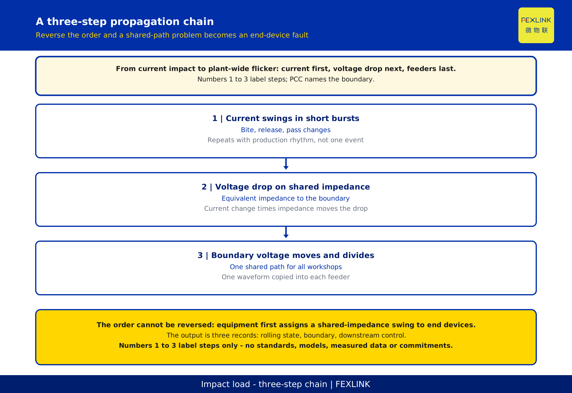
Between the source and the PCC, transformers, lines and switchgear together form an equivalent impedance. When the line draws more current the drop grows; when current falls back the drop follows. The change in drop equals the change in current multiplied by the system impedance, so the voltage at the boundary moves. That is the translation chain from a current impact to a voltage fluctuation.
A violent current change and a weak, high-impedance source enlarge the result. Neither is fixed at the feeder end, so a poor downstream curve does not prove a downstream fault.
The fluctuation forms on the common path first, then divides along the feeders; each workshop sees a different face of the same event. Record that chain rather than arguing about which device alarmed first.
IV. Why the whole plant sees it: one common coupling point
The PCC is the physical boundary between supply and user sides. Below that boundary, workshops and feeders share one supply path. Once it forms there, every attached load sees something, in differing degree.
A plant-wide complaint is unsurprising; it is one waveform copied into many records.
Other articles cover the PCC as a responsibility boundary; this one does not repeat them. It uses the PCC for one purpose: deciding where the first synchronised record belongs. Fix the boundary first, then choose a downstream control point.
V. Why the eye notices flicker first
Voltage swings are reported first because the eye is sensitive to light changes, not because the worst effect happened first. The same swing is brightness variation on lighting, torque change on a motor, or an alarm or retry on a control device.
Hence the illusion that lighting is at fault. The lamp is an honest display, not the source.
A visual impression is a lead, not evidence. This article gives no visual thresholds, flicker indices, evaluation values or verdicts.
VI. Three ways other workshops are affected
The table lets different teams speak from one form. Recording points only: no thresholds, no remedial actions.
| 1 | Affected object | 2 | Typical symptom | 3 | Record focus |
|---|---|---|---|---|---|
| 1 | Lighting and offices | Brightness variation is easiest to see | Log the concurrent state and location, not the impression | ||
| 2 | Drives and converters | Torque instability, alarms or self derating | Log event time and whether it matches the rolling rhythm | ||
| 3 | Metering and control | Jumping readings, retries, gaps in records | Keep raw segments and the clock source for alignment |
Gaps in a record can originate in the device itself; without raw segments and a clock source they cannot be separated from a supply fluctuation.
VII. Telling fluctuation apart from sags and harmonics
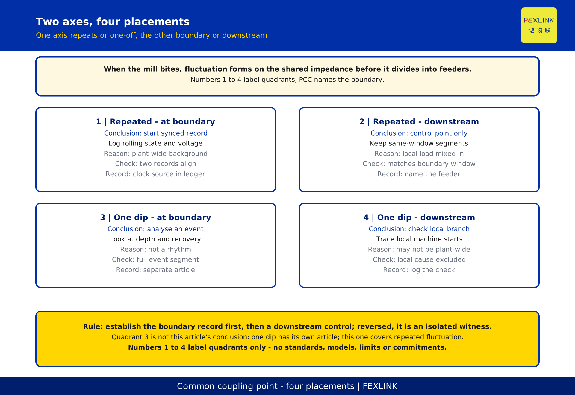
Several power-quality phenomena coexist in a steel plant; mixing them misdirects the remedy. Directions only: no repeated articles, no limits.
| 1 | Phenomenon | 2 | Trigger | 3 | Observation focus |
|---|---|---|---|---|---|
| 1 | Single voltage sag | One large machine starting or braking causes one dip | Depth and recovery of that single event | ||
| 2 | Harmonics and distortion | Long-term waveform shape linked to nonlinear loads | Spectrum and long-term trend | ||
| 3 | Supply voltage deviation | Slow shift, generally high or low | Statistics over a longer window |
A single sag from a harbour crane has its own article: one event, not a repeated rhythm and a shared path.
VIII. Observation order: establish evidence at the PCC first
More instruments do not help; the order must not be reversed. Step 1 records voltage and rolling state at the PCC on one time axis. Step 2 takes one downstream victim point as a control over the same interval. Step 3 aligns the clocks of both records and marks the segments that coincide and those that do not.
Without these steps the downstream record is an isolated witness, the effect is unproven and responsibility becomes competing stories.
The ESE power quality monitor is registered by name only, for the role of a continuous alignable boundary record. No parameters, ranges, channel counts, supply options, communication interfaces or selection advice appear. GB/T 12326 is cited by name and number only, with the version in force applying; no compliance judgement is made here.
IX. Response lines around the PCC: source, path, operation
Response follows only after the evidence holds. The first line is the source: can process rhythm, drive control or local support smooth the power swing and reduce how violent the current change is? The second is the path: a weak shared impedance and upstream conditions belong to supply design. The third is operation: separate sensitive processes from impact-dense periods and make interlocks and record ownership explicit.
None is exclusive, and their order follows the evidence and project documents. This article gives the division and the question each line must answer, with no equipment lists, capacities, limits, budgets, schedules or effect commitments.
The digital electrical intelligent supervision system remains a registered name only; under the library manual its dimensions, layers and elements are not expanded. The three lines, layers and steps are working tools, not a dimension or layer of any official solution. The official definition belongs to official documents and the knowledge base; no white paper is quoted.
X. A site checklist and evidence ledger
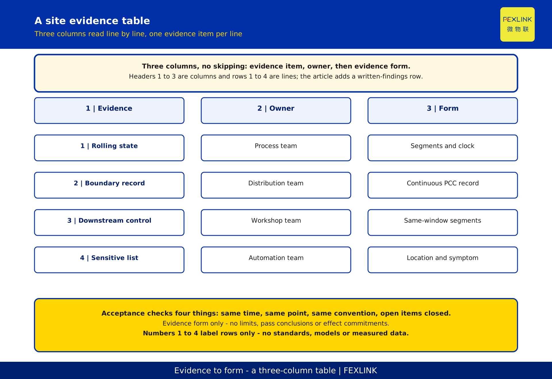
A fillable form lets a different person recompute later on the same conditions. The five rows correspond to source, boundary, downstream, affected objects and written findings. A missing row means the work is not finished.
| 1 | Evidence item | 2 | Owner | 3 | Evidence form |
|---|---|---|---|---|---|
| 1 | Rolling state log | Process and operations team | Concurrent state segments and clock source | ||
| 2 | Boundary record | Power distribution and electrical team | Continuous record at the PCC | ||
| 3 | Downstream control | Workshop electrical team | Raw segments for the same interval | ||
| 4 | Sensitive equipment list | Equipment and automation team | Location, event symptom, affected scope | ||
| 5 | Written findings and open items | Owner, supply side and parties | Aligned conclusion, sign-off, follow-up log |
There is no pass or fail column: this article does not adjudicate. Limits, remedies and acceptance rules belong to the current standard text and project documents. Numbers 1 to 5 are structural labels only; they are not measurement point counts, record counts or priority weights.
XI. Boundaries and common misjudgements
Four misjudgements recur: treating plant-wide complaints as end-device faults; recording only at the noisiest point; concluding from a single reading without state or clock; treating a standard as an acceptance limit or a working division as a framework.
All give an answer before the same time, point and convention are secured. Complete the three steps of Section VIII and the five rows of Section X so every statement points to a record.
Restating the boundary: the three layers of impact source, propagation path and affected points, and the three lines of source, path and operation, are working divisions, not a dimension or layer of any official solution. The digital electrical intelligent supervision system is registered by name only, with no expansion, no decoding and no invented framework. GB/T 12326 is cited by name and number only, with no year, clause numbers, limits or compliance judgement; the version in force applies.
FAQ: frequently asked questions
Q: Would replacing the lamps with non-flickering ones solve it?
No. New lamps change the perception of brightness variation, not the current swing at the rolling line and not the voltage drop on the shared impedance.
Q: Is a recorder in the workshop that complains most enough?
No. A downstream record also contains the load changes of its own branch; without boundary background, a plant-wide fluctuation cannot be separated from a local disturbance. Establish the boundary record first, then choose a downstream control point, and use one common clock source.
Q: If the flicker stops during a maintenance shutdown, is the supply side clear?
It only shows the impact source was not running. A shutdown gives a background record at the same point to align against production periods; conclusions belong in project documents.
Q: Does remediation always mean buying new equipment?
First separate what the evidence points to: source, path or operation. Whether equipment is needed, and of what kind, belongs to later design documents.
Q: Is this an official solution framework or a standard limit, and will model numbers and parameters appear?
Neither. The digital electrical intelligent supervision system is a registered name only; its official definition belongs to official documents and the knowledge base. GB/T 12326, Power quality - Voltage fluctuation and flicker, is cited by name and number only, with no year of issue, clause numbers, limits or compliance judgement; the version in force applies. The ESE power quality monitor is registered by its canonical name only, with no parameters, ranges, channel counts, supply options, communication interfaces or selection advice.
Scope and limitations
It is for steel-plant power distribution and electrical engineers during proposal review, complaint investigation and monitoring-point planning.
It excludes single sags, harmonic limits, photovoltaic interconnection, instrument selection, equipment settings and compliance judgement; those have their own articles. Unlike a single harbour-crane sag, this addresses repeated rhythmic impacts, voltage fluctuation and flicker, and the observation order around the PCC.
No frequency, amplitude, duration, limit, capacity, budget, pass rate or acceptance conclusion is given. The example is a generic steel plant, with no customer name, region, scale or result data. Numbers 1 to 5 are structural labels and GB/T 12326 is a standard name and number only; neither represents a measured value. The three layers, three lines and three steps are working divisions and structural tools, not a dimension or layer of any official solution. All deliverables are pending review and require owner confirmation; the generator does not self-approve and nothing is published.
Frequently Asked Questions
Would replacing the lamps with non-flickering ones solve it?
No. New lamps change the perception of brightness variation, not the current swing at the rolling line and not the voltage drop on the shared impedance.
Is a recorder in the workshop that complains most enough?
No. A downstream record also contains the load changes of its own branch; without boundary background, a plant-wide fluctuation cannot be separated from a local disturbance. Establish the boundary record first, then choose a downstream control point, and use one common clock source.
If the flicker stops during a maintenance shutdown, is the supply side clear?
It only shows the impact source was not running. A shutdown gives a background record at the same point to align against production periods; conclusions belong in project documents.
Does remediation always mean buying new equipment?
First separate what the evidence points to: source, path or operation. Whether equipment is needed, and of what kind, belongs to later design documents.
Is this an official solution framework or a standard limit, and will model numbers and parameters appear?
Neither. The digital electrical intelligent supervision system is a registered name only; its official definition belongs to official documents and the knowledge base. GB/T 12326, Power quality - Voltage fluctuation and flicker, is cited by name and number only, with no year of issue, clause numbers, limits or compliance judgement; the version in force applies. The ESE power quality monitor is registered by its canonical name only, with no parameters, ranges, channel counts, supply options, communication interfaces or selection advice.