 FEXLINK Research Institute
The short answer
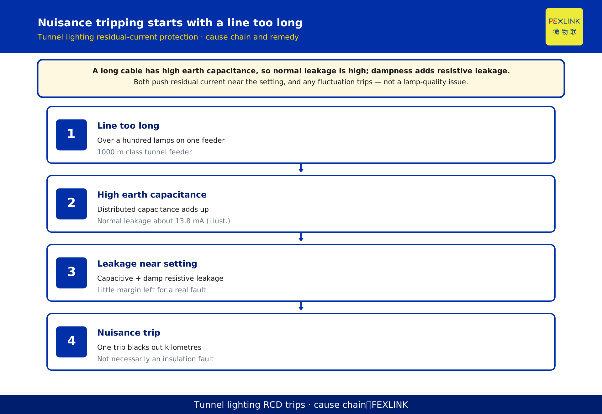
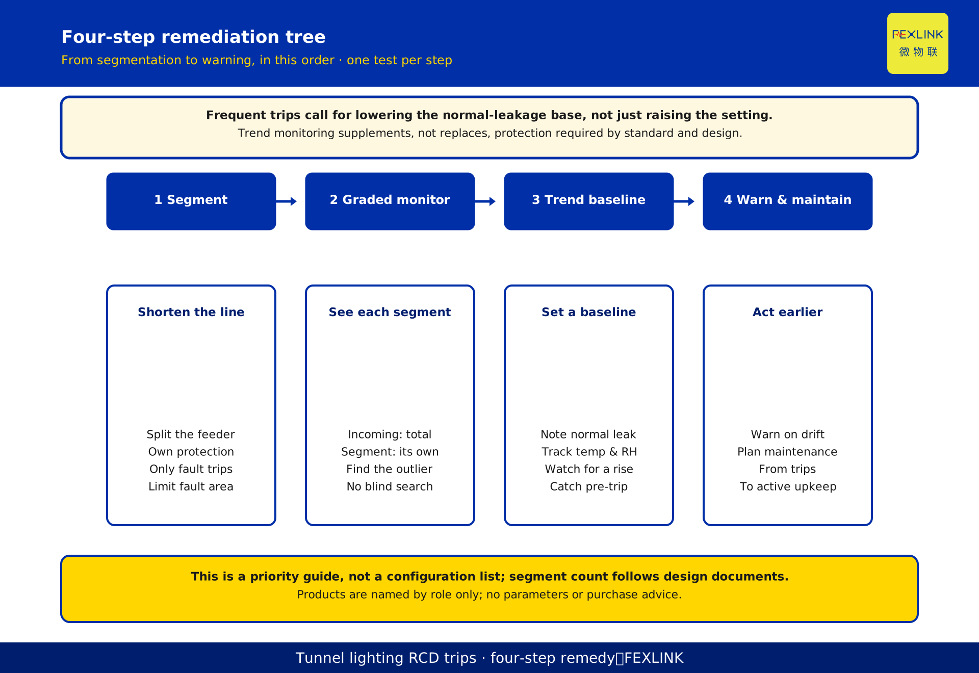
Recurrent tripping of residual-current protection on tunnel lighting is rooted in line length, not lamp quality. A long cable has large earth capacitance, so even a healthy circuit carries appreciable capacitive leakage, which dampness adds to. The two push residual current toward the setting, and any fluctuation trips the device. The answer is not to disable protection but to segment the supply so a fault is localised, monitor leakage per segment, and protect on the leakage trend rather than a single threshold. This article covers mechanism and monitoring only; it gives no specific settings or parameter commitments.
The symptom: one trip blacks out kilometres
A tunnel lighting circuit runs the tunnel's length, often feeding over a hundred luminaires on one feeder, the cable laid near trays, sprinklers and rock. A typical scene is a trip at night or after rain: one feeder's residual-current device operates and the whole tunnel goes dark. On reclosing, it may hold briefly and trip again, or refuse to close. A megger insulation test reads acceptably high, yet the device keeps operating.
The habit is to equate residual-current operation with an insulation fault and hunt for damaged insulation. In a long circuit the trigger need not be a real fault: capacitive leakage is appreciable, and dampness raises resistive leakage; together they easily cross the threshold. The first step is not to inspect every lamp, but to find the circuit's inherent leakage in normal operation.
Where the capacitance of a long cable comes from
A cable is often imagined as an ideal conductor: current leaves on the live wire and returns on the neutral, nothing flowing to earth. In a real long cable, every section of live and neutral conductor forms a small capacitance to earth — the conductor is one plate, earth and the screen the other, insulation the dielectric. Over hundreds or thousands of metres these capacitances add up and can no longer be ignored.
A capacitor passes alternating current: at power frequency it lets a portion pass through the dielectric to earth, which is capacitive leakage. It has nothing to do with damaged insulation — a new cable has it too — and grows with length and surface area. The tunnel difficulty is that many luminaires are strung on one long feeder. What is negligible in a short circuit becomes the dominant issue in a tunnel.
Estimating capacitive leakage: a reproducible worked example
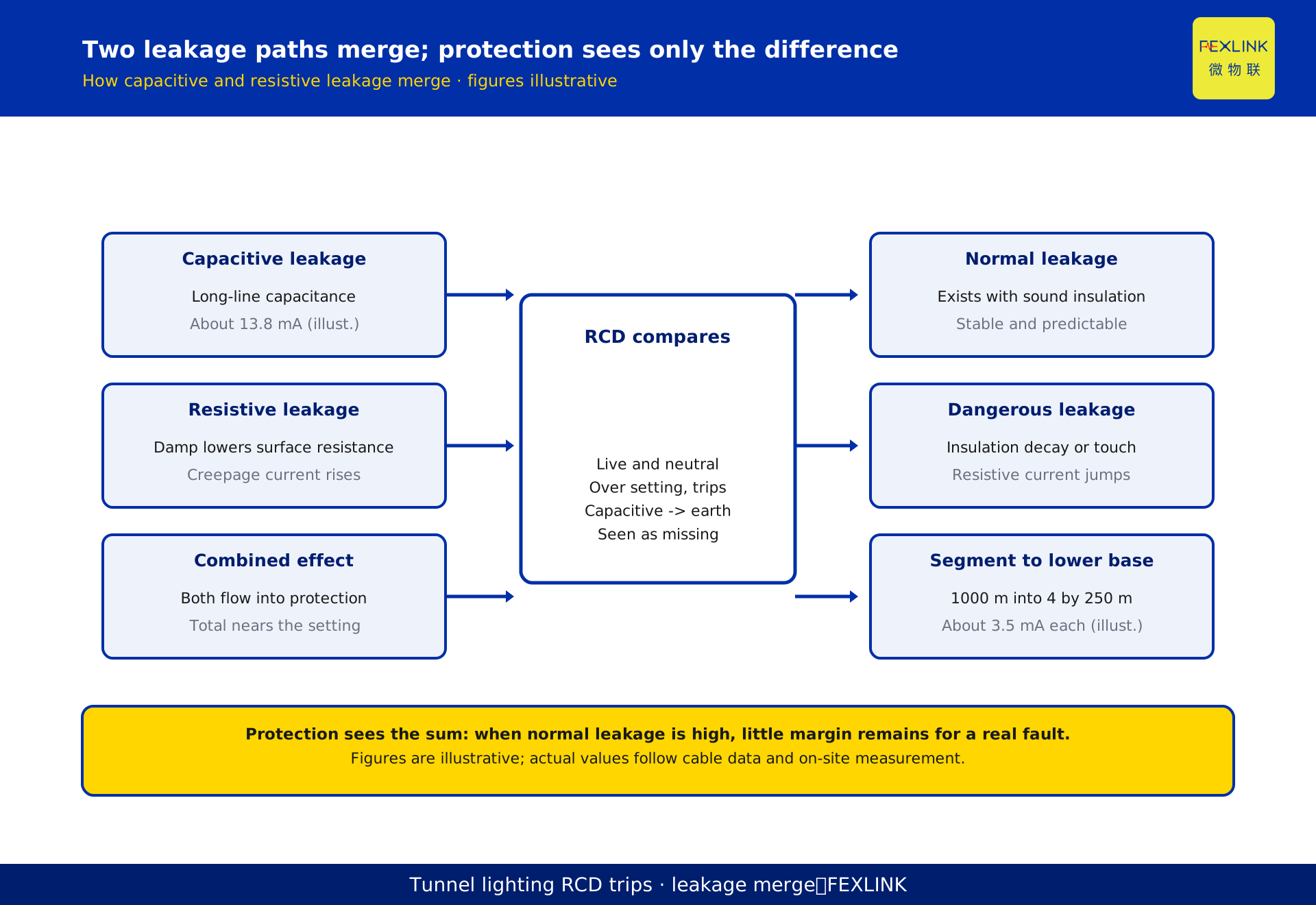
Capacitive leakage can be estimated from a basic AC relation: current equals two times pi times frequency times earth capacitance times phase voltage. The numbers below are a constructed, desensitised illustration of magnitude and method. Assume a tunnel lighting feeder 1000 m long, earth capacitance about 0.2 microfarad, at 50 Hz and 220 V. Substituting: the capacitive leakage is about 2 x 3.14 x 50 x 0.2 x 10^-6 x 220, roughly 13.8 mA (illustrative). Now segment: split the 1000 m into 4 segments of 250 m each; with capacitance proportional to length, each is about 0.05 microfarad and its leakage about 3.5 mA (illustrative). The per-segment background falls to about a quarter, easing the distinction between normal leakage and a real fault.
| Item | Illustrative input | Calculation | Result (illustrative) |
|---|---|---|---|
| Whole-feeder capacitive leakage | 0.2 microfarad, 50 Hz, 220 V | 2 x 3.14 x 50 x 0.2 x 10^-6 x 220 | about 13.8 mA |
| Single segment after a 4-way split | 250 m, about 0.05 microfarad | scaled by length | about 3.5 mA |
All values are illustrative; actual figures depend on cable type and site conditions and must be measured.
Normal leakage and dangerous leakage are not the same
Tripping has a deeper cause: two different currents are lumped together. One is normal leakage — the capacitive current of a long cable plus the small resistive current that exists even with sound insulation. It is stable, drifting slowly with temperature and humidity, and forms the circuit's background. The other is dangerous leakage: when insulation deteriorates or is damaged, or a person touches a live part, resistive leakage rises abruptly and persists. That is the signal protection must clear.
The device sees the sum of the two. When the normal background is high, the margin for dangerous leakage is narrow: a small fluctuation can push the total past the setting and trip. Conversely, raising the setting to avoid nuisance trips may let a genuine small dangerous leakage pass. Hence the dilemma: a low setting means frequent nuisance trips, a high setting means lost protection. The way out is not to agonise over one setting but to lower the background first — exactly what segmentation does.
Why the protection keeps tripping: setting versus capacitance
A residual-current device (RCD) compares live and neutral currents and trips when the difference exceeds its setting. The logic is sound; the mismatch is between setting and circuit. Normal capacitive leakage in a long circuit is indistinguishable to the RCD: it leaves the live conductor through distributed capacitance to earth and does not return on the neutral, so the RCD counts it as missing current. Physically it is not an insulation fault but the normal operating current of a capacitor.
Worse, capacitive leakage varies with voltage and switching. Tunnel lighting is often switched in groups: more lamps and more energised length mean more leakage, and a setting fine at light load may trip repeatedly at full load. With the magnitudes in the example, a long circuit's normal leakage already sits close to the threshold, leaving no margin for a genuine fault. Nuisance tripping is therefore not a failed device or a casual adjustment — it is a structural conflict between long-circuit capacitance and single-threshold protection.
Why dampness makes it worse
A tunnel is damp: rock seepage, sprinklers and condensation keep cable joints, lamp holders and boxes in moisture. Dampness directly raises resistive leakage: once insulation surfaces absorb water, surface resistance falls and creepage current grows, adding to capacitive current and pushing total leakage higher.
Humidity lags and fluctuates: leakage rises after rain, in the early morning and with poor ventilation, and falls after drying. That explains why the same circuit trips sometimes and not others. It is not the fault that is unpredictable; it is the humidity. More subtly, moisture gradually degrades insulation, so normal resistive leakage creeps up over months, and a single measurement is easy to misread.
This article cites GB 13955 only as a standard number and a qualitative description of coverage: no year, clause or operating limit is quoted, and no milliampere figure is treated as a standard requirement. Dampness and leakage are explained as mechanism only; actual criteria follow the current standard text, design documents and on-site measurement.
Segmentation: shrinking the fault footprint
Since the conflict roots in a circuit too long and too capacitive, the direct remedy is to shorten it — segment the supply. Split one long feeder into several independent segments, each with its own protection. Three things change. Each segment's earth capacitance falls in proportion to length, so normal leakage drops from about 13.8 mA to about 3.5 mA per segment. A fault in one segment trips only that segment rather than blacking out the whole tunnel, localising the fault footprint. And because leakage levels differ between segments, a segment running high is obvious and investigation gains direction.
Segmentation is not the finer the better: more segments mean more boxes, protection devices, cable and maintenance complexity. A sound scheme depends on tunnel length, luminaire distribution and maintenance access, and is fixed by the design documents.
Distinction from the companion chemical-plant piece: that piece deals with separating resistive from capacitive leakage; this one deals with a tunnel feeder that nuisance-trips from excess capacitance and with using segmentation to shrink the fault footprint. They address different problems.
Graded leakage monitoring: eyes on every segment
After segmentation, each segment's leakage state must be visible, calling for monitoring on the incoming supply and on each segment — a graded scheme. The main feeder watches the total and overall trend; each segment watches its own leakage and locates an abnormal one. If a segment stays high, investigate that segment rather than searching blindly along kilometres of tunnel.
The Fexlink ESC multi-circuit leakage monitoring and control unit provides multi-circuit measurement and centralised collection; the Fexlink ESF electrical fire monitoring unit covers leakage- and temperature-related fire monitoring; the digital electrical intelligent supervision system aggregates segment data for remote viewing and alarms. These are named by role only: no range, accuracy or channel-count parameters are given, and specifications follow product data.
With graded data, protection can move from one-size-fits-all to per-segment management: normal segments keep routine protection, abnormal ones get closer attention, without sacrificing safety or repeated blackouts.
Trend monitoring instead of a single threshold
A single current threshold has a fundamental flaw: it looks only at how big the current is now, not at whether it is worsening. Insulation deterioration is a process, and a slow rise in leakage is itself an early signal. Trend monitoring sets a normal-leakage baseline for each segment and tracks it over time, humidity and temperature. When leakage has not crossed the trip threshold but keeps departing from its own baseline and rising, an early warning and planned maintenance catch the problem before a trip.
The benefits are three: turning nuisance trips into warnings and avoiding needless blackouts; catching early insulation deterioration and shifting from reactive tripping to planned maintenance; and accumulating leakage history to inform segmentation and settings. Trend monitoring does not replace residual-current protection. Safety protection must still follow the current standard and design; trend data is a supplement for better operation and fewer nuisance trips, not a reason to reduce protection.
Where the products and solution fit
Mapping onto devices, each link has a role. The ESC multi-circuit leakage monitoring and control unit carries out multi-segment measurement and centralised collection and is the data source for graded monitoring. The ESF electrical fire monitoring unit covers leakage- and temperature-related fire monitoring. The digital electrical intelligent supervision system aggregates segment data into a monitorable, alarm-capable whole. They correspond to watching leakage by segment, watching fire risk and supervising centrally. These products are described by function only: no parameters are expanded, no effects promised, and no purchase advice given.
FAQ
Q: If protection keeps tripping, isn't raising the setting enough?
No. Raising it masks the conflict: high normal leakage means a capacitive feeder, and a higher setting reduces nuisance trips but may let a genuine dangerous leakage pass. Segment first to lower each segment's normal leakage, then use graded monitoring to tell normal fluctuation from a real fault.
Q: Insulation resistance reads fine — why does it still trip?
Because they are different things. A megger measures resistive insulation and cannot see leakage from distributed capacitance. A long cable with intact insulation still carries appreciable capacitive current, which protection counts into the difference. Passing an insulation test does not mean no nuisance tripping.
Q: Why does the same circuit trip sometimes and not others?
Usually humidity. After rain, in the early morning or with poor ventilation, resistive surface leakage rises and, added to capacitive leakage, crosses the threshold; it falls after drying. The unpredictability is environmental variation, not a fault appearing and disappearing.
Q: Does segmentation add a lot of cost?
It adds boxes, protection devices and cable, but buys a smaller fault footprint, fewer nuisance trips and faster investigation. More segments are not automatically better; the count depends on tunnel length, luminaire distribution and maintenance access, fixed by the design documents. This article gives no specific segment count.
Q: This piece or the chemical-plant one — which should I read?
It depends on the problem. For separating resistive from capacitive leakage on a chemical-plant cable, read that piece. For why a tunnel feeder nuisance-trips and how segmentation plus graded monitoring solve it, read this one; the contribution here is segmentation to shrink the fault footprint.
Scope and limitations
- This article applies to residual-current protection nuisance tripping on long, damp circuits such as road and rail tunnel lighting, covering mechanism and segmented monitoring. Short circuits and dry indoor settings may trip for other reasons and are outside scope.
- The figures 1000 m, 0.2 microfarad, 50 Hz, 220 V, 13.8 mA, 4 segments, 250 m, 0.05 microfarad and 3.5 mA are constructed, desensitised assumptions used only to demonstrate the algorithm and magnitude; they match no real tunnel and are not a setting basis. Actual values follow cable parameters, site conditions and measurement.
- This article cites GB 13955 only as a standard number and a qualitative description of coverage; no year, clause, operating limit or setting parameter is quoted. Actual criteria follow the current standard text, design documents and on-site verification; this is not a mandatory technical requirement.
- Associated products and the solution are registered by name and functional role only; no range, accuracy, channel count or interface parameters are expanded, no functions are fabricated, and no purchase advice is given.
- Performance data such as energy-saving rate, accuracy, nuisance-trip reduction and payback are excluded from the conclusions. Final judgements about blackouts or electric shock rest with qualified parties; this is not a safety commitment.
Frequently Asked Questions
If protection keeps tripping, isn't raising the setting enough?
No. Raising it masks the conflict: high normal leakage means a capacitive feeder, and a higher setting reduces nuisance trips but may let a genuine dangerous leakage pass. Segment first to lower each segment's normal leakage, then use graded monitoring to tell normal fluctuation from a real fault.
Insulation resistance reads fine — why does it still trip?
Because they are different things. A megger measures resistive insulation and cannot see leakage from distributed capacitance. A long cable with intact insulation still carries appreciable capacitive current, which protection counts into the difference. Passing an insulation test does not mean no nuisance tripping.
Why does the same circuit trip sometimes and not others?
Usually humidity. After rain, in the early morning or with poor ventilation, resistive surface leakage rises and, added to capacitive leakage, crosses the threshold; it falls after drying. The unpredictability is environmental variation, not a fault appearing and disappearing.
Does segmentation add a lot of cost?
It adds boxes, protection devices and cable, but buys a smaller fault footprint, fewer nuisance trips and faster investigation. More segments are not automatically better; the count depends on tunnel length, luminaire distribution and maintenance access, fixed by the design documents. This article gives no specific segment count.
This piece or the chemical-plant one — which should I read?
It depends on the problem. For separating resistive from capacitive leakage on a chemical-plant cable, read that piece. For why a tunnel feeder nuisance-trips and how segmentation plus graded monitoring solve it, read this one; the contribution here is segmentation to shrink the fault footprint.