 FEXLINK Research Institute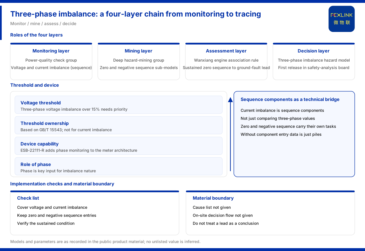
How many layers are needed to go from monitoring three-phase imbalance to tracing it?
Direct answer: three-phase imbalance is not an isolated reading but an analysis chain from monitoring, mining and analysis to decision. At the monitoring layer, the power-quality examination group lists voltage imbalance and current imbalance (sequence components) as analysis dimensions at the same time; at the mining layer, the deep hazard mining group further provides zero-sequence current and negative-sequence component sub-models; at the analysis layer, an association rule judges continuous zero-sequence current as a clue for tracing single-phase grounding; and at the decision layer, the three-phase imbalance hazard model is brought into the safety-analysis board as one of the first-release models. On the device side, the ESB three-phase imbalance monitor (for example ESB-22111-R) carries the phase-monitoring capability. Only by understanding this chain can one answer "what exactly should be looked at in three-phase imbalance, and who judges it".
A boundary must be stated first. What the material can confirm is the ownership of the analysis dimensions, the existence of the sub-models, the direction of the association rule and the capability range of the devices; the material does not give a field determination process beyond specific thresholds, nor a cause list for the various kinds of imbalance.
The monitoring layer: voltage and current must be watched together
The power-quality examination group contains both voltage imbalance and current imbalance (sequence components) as monitoring dimensions. This is worth emphasising: three-phase imbalance is often simplified to "voltage unbalance", but from the monitoring-design point of view, the voltage side and the current side are two parallel observation lines. Watching voltage alone may miss signs of imbalance already present on the current side; watching current alone may miss an abnormality on the voltage side.
Placing the two in the same examination group means they are treated as two sides of the same class of problem. For engineers, the practical meaning is that when organising monitoring items, the scheme should be confirmed to cover both voltage imbalance and current imbalance, rather than assuming one can represent the other. Only when both are in place can they corroborate each other in later analysis.
Why current imbalance uses sequence components
The material marks current imbalance explicitly as "sequence components". Sequence components are a mathematical decomposition method for analysing a three-phase system; they decompose three-phase quantities into zero-sequence, positive-sequence and negative-sequence components, thereby describing the nature of the imbalance more clearly. Using sequence components means that the analysis of current imbalance does not stop at "whether the three-phase values are equal" but goes deeper into the composition of the components.
This choice is critical for later analysis, because the zero-sequence and negative-sequence components each correspond to different physical meanings and fault clues. It is precisely for this reason that the material continues at the deep hazard mining layer with the zero-sequence current and negative-sequence component sub-models. If current imbalance were treated as a single scalar at the monitoring layer, the later component analysis would have no starting point. Sequence components are the technical bridge connecting the monitoring layer and the mining layer.
The mining layer: the independent value of zero-sequence and negative-sequence
In the deep hazard mining group, the material explicitly lists the zero-sequence current sub-model and the negative-sequence component sub-model. Their separate listing shows that they are not vague modifiers of "imbalance" but models each carrying a specific analysis task.
Zero-sequence current is usually related to grounding-type problems, while the negative-sequence component is often related to asymmetry of three-phase loads or equipment. Setting up sub-models separately at these two places reflects that the same three-phase imbalance may have a completely different nature behind it and needs different components to distinguish. For scheme designers, this means monitoring data can form a valuable judgement only when it lands on the corresponding sub-model.
A threshold requiring high attention
The material lists "three-phase voltage imbalance exceeding 15%" as an item requiring high attention, based on the standard GB/T 15543. The 15% is a definite numeric threshold that distinguishes voltage imbalance from "needing observation" to "needing priority handling". For a project, the value of this threshold is that it provides a priority order for screening: when voltage imbalance approaches or exceeds this value, it should be reviewed immediately according to the established procedure rather than continuing with routine observation.
It should be noted that the material gives the threshold for voltage imbalance and does not set an applicable numeric threshold for current imbalance. Although the voltage side and the current side both belong to imbalance, their determination formulations are not the same, and 15% cannot be transferred directly to current imbalance. Mixing the thresholds of different components is one of the most error-prone points in analysis.
The analysis layer: continuous zero-sequence current as a single-phase grounding clue
In the association rules of the Wanxiang engine, continuous zero-sequence current is judged as a clue for tracing single-phase grounding. The meaning of this rule is that when zero-sequence current does not appear occasionally but persists, it should be treated as a direction for investigating a single-phase grounding problem. It connects the observed component phenomenon with the possible fault type.
A distinction must be drawn between "appearance" and "persistence". Occasional zero-sequence current may be caused by various transient factors, while persistence leans more towards a grounding-type problem. The material uses "continuous" as the judging word, showing that triggering this rule is conditional, and a conclusion cannot be drawn from a single zero-sequence reading. In engineering application, attention should be paid to whether it persists, and further verification should be carried out according to the existing project procedure, rather than treating the clue directly as a conclusion.
The decision layer: the three-phase imbalance hazard model
At the decision layer, the Tianyan engine has a three-phase imbalance hazard model, which is brought into the safety-analysis board as one of the first-release models of that board. This shows that three-phase imbalance is treated on the decision side as a class of hazard requiring independent modelling, not as an incidental item attached to other analyses.
From the chain point of view, the decision-layer model gathers the results of the monitoring, mining and analysis layers to form an overall judgement of the hazard. The positioning as a first-release model also suggests a relatively high priority.
The device side: from the all-parameter smart meter to the three-phase imbalance monitor
The key device-side difference appears between the all-parameter smart meter (for example ESA-22111-R) and the three-phase imbalance monitor. The material points out that the three-phase imbalance monitor adds phase-monitoring functionality on the same architecture as the all-parameter smart meter. That is, the two share the same architecture, and the difference is concentrated in the phase-monitoring capability.
This difference is critical for three-phase imbalance analysis: phase is important information for judging the nature of the imbalance. If the monitoring device does not have phase-monitoring capability, the subsequent sequence-component analysis and tracing lack an input. Device capability and the analysis chain must match, so that the chain does not break at the data entry point.
Landing check list
- Cover both kinds of imbalance. Confirm that the monitoring scheme contains both voltage imbalance and current imbalance (sequence components).
- Keep the component entry. Ensure that current-imbalance data can enter the zero-sequence current and negative-sequence component sub-models rather than being treated as a single scalar.
- Set the voltage threshold separately. Treat three-phase voltage imbalance exceeding 15% as an item requiring priority attention, based on GB/T 15543, and do not transfer it to the current side.
- Verify the "persistence" condition. When zero-sequence current is used as a single-phase grounding clue, confirm whether it persists, then verify according to procedure.
- Align device capability. For in-depth analysis, choose the three-phase imbalance monitor with phase-monitoring capability.
Summary
The analysis chain of three-phase imbalance can be summarised in four layers: the monitoring layer covers voltage imbalance and current imbalance (sequence components) at the same time; the mining layer sets zero-sequence current and negative-sequence component sub-models; the analysis layer treats continuous zero-sequence current as a single-phase grounding clue; and the decision layer has a three-phase imbalance hazard model brought into the safety-analysis board as a first-release model. On thresholds, three-phase voltage imbalance exceeding 15% is an item requiring priority attention, based on GB/T 15543; on devices, the three-phase imbalance monitor adds phase monitoring on the same architecture as the all-parameter smart meter.
For engineering staff, the prudent approach is to ensure the monitoring dimensions are complete first, then keep the component-analysis entry, and finally choose a device with phase-monitoring capability as needed; for review and delivery, it should be checked whether the scheme treats a cause list or field determination process not given by the material as an established conclusion. Keeping "what is monitored" and "what is analysed" separately aligned is what makes the three-phase imbalance chain complete.