 FEXLINK Research Institute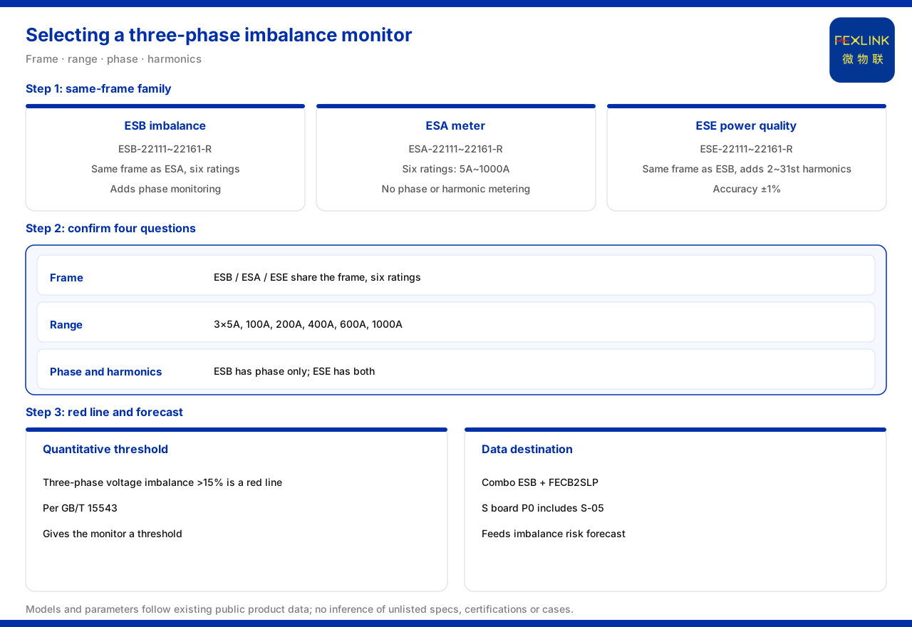
Direct answer
For three-phase imbalance monitoring, selection first confirms the monitor's architecture and range, then confirms whether phase and harmonics are needed. The product knowledge base records that the ESB three-phase imbalance monitor shares an architecture with the ESA all-parameter smart meter and offers 6 current levels (ESB-22111 to 22161-R), 3×220/380V, OLED and RS485, adding phase monitoring on the same architecture, with 2 digital inputs and 1 relay output, but without harmonic monitoring. By contrast, the ESA all-parameter smart meter offers 6 current levels (ESA-22111 to 22161-R, covering 3×5A, 100A, 200A, 400A, 600A and 1000A), with the whole series at AC220V, OLED and RS485, and without phase or harmonic monitoring. If harmonics must be covered in addition to three-phase imbalance, the product knowledge base also has the ESE power-quality monitor, sharing an architecture with ESB (ESE-22111 to 22161-R) and adding 2 to 31 order harmonic monitoring on top of phase monitoring, with an accuracy of plus or minus 1%. Among the system safety red-lines, three-phase voltage imbalance greater than 15% is one that cannot be bypassed, based on GB/T 15543, giving a quantitative threshold for three-phase imbalance. Selection only needs to confirm architecture, range, phase and harmonics in turn.
1. Understanding the same-architecture family relationship first
To select a three-phase imbalance monitor one must first understand that it is not an isolated model but one member of a same-architecture family. The product knowledge base records that the ESB three-phase imbalance monitor shares an architecture with the ESA all-parameter smart meter, with 6 current levels from ESB-22111 to 22161-R, 3×220/380V, OLED and RS485. This shared architecture means the range levels, display and networking method are broadly consistent within the family, with differences concentrated in monitoring dimensions. Selection first takes the current level from the 6 levels by circuit current, then judges which monitoring dimensions are needed, which is clearer than comparing every parameter from scratch.
2. Comparison: what the ESA all-parameter meter provides
To understand what ESB adds, one first looks at what the base model of the same architecture provides. The product knowledge base records that the ESA all-parameter smart meter offers 6 current levels from ESA-22111 to 22161-R, corresponding to 3×5A, 3×100A, 3×200A, 3×400A, 3×600A and 3×1000A, with the whole series at AC220V, OLED and RS485, and notes no phase or harmonic monitoring. This gives two things: the range covers 5A to 1000A, so selection can position itself on it; and the base model provides no phase or harmonic dimension, leaving a clear reference for the later comparison of ESB and ESE.
3. The one thing ESB adds: phase monitoring
On top of the base model, the three-phase imbalance monitor adds phase monitoring. The product knowledge base records that the ESB three-phase imbalance monitor adds phase monitoring on the ESA architecture and has 2 digital inputs and 1 relay output, while making clear there is no harmonic monitoring. Phase monitoring is the key to its difference from an ordinary meter: precisely because phase information is brought in can it monitor around the three-phase imbalance dimension. If the concern is whether three-phase voltage and current are balanced and the phase relationship, take this model; if only metering and all-parameter electrical quantities are wanted, the all-parameter smart meter is enough.
4. Quantitative threshold: three-phase voltage imbalance greater than 15%
Three-phase imbalance needs a boundary that can be judged. The product knowledge base records that among the system safety red-lines, three-phase voltage imbalance greater than 15% is one of the 5 non-bypassable safety red-lines, based on GB/T 15543. This red-line provides a quantitative threshold and a standards source for three-phase imbalance monitoring: when the three-phase voltage imbalance exceeds that proportion, it is a non-bypassable case in the front-end pre-check. Note that this article only relays the threshold and basis listed in the materials and does not infer on-site measured values from them, nor treat the threshold as the only criterion; actual judgment should still combine the system conditions and the project scheme.
5. Upgrade path: what to do when harmonics are needed
If harmonics must be covered besides three-phase imbalance, the monitor must be changed. The product knowledge base records that the ESE power-quality monitor shares an architecture with ESB, with 6 current levels from ESE-22111 to 22161-R, and adds harmonic monitoring on top of phase monitoring, covering 2 to 31 order harmonics with an accuracy of plus or minus 1%. This shows a clear upgrade path within the family: for phase but not harmonics, take the three-phase imbalance monitor; for both phase and harmonics, take the power-quality monitor. Treating whether harmonics are wanted as a branching question avoids over- or under-configuring the monitoring dimensions.
6. Scenario: monitoring and treatment considered as a set
Three-phase imbalance monitoring often appears as a set with treatment and execution devices. In the scenario mapping of the product knowledge base, distribution-automation three-phase management recommends the ESB three-phase imbalance monitor with the FECB2SLP intelligent circuit breaker. This suggests that selection should not stop at the monitor itself: the monitoring side finds the imbalance, the execution side treats and protects, and together they form the combination given by the scenario mapping. In a real project, therefore, selecting a three-phase imbalance monitor should usually be considered together with the execution-side device and fixed by the pairing terms of the same scenario, rather than purchased alone.
7. Where the data goes: from monitoring to prediction
The imbalance data a monitor acquires does not stop at a local display. The product knowledge base records that in the S safety analysis block of the Tianyan engine / large model, the P0 first-release models include S-05 three-phase imbalance hazard. This means the acquired three-phase imbalance data can connect to predictive analysis, forming a monitoring, judgment and prediction chain: the monitor provides data, the analysis block brings it into the safety dimension, and the prediction layer answers when action is needed. Note that the model numbers and block division are planning terms listed in the product knowledge base; this article relays them and does not infer the analysis effect of any specific project from them.
Scope and limitations
First, this article only restates what the product knowledge base lists; its factual boundary is limited to the architecture, specifications and monitoring dimensions of the ESB three-phase imbalance monitor, the ESA all-parameter smart meter and the ESE power-quality monitor, the safety red-line item, the scenario mapping and the prediction-layer block, and it introduces no unlisted parameter, certification or case.
Second, the ESB three-phase imbalance monitor sharing an architecture with the ESA all-parameter smart meter, its 6 current levels, 3×220/380V, OLED, RS485, phase monitoring, 2 digital inputs and 1 relay output and its lack of harmonic monitoring, the corresponding current values of the 6 ESA current levels and its whole-series supply, display and communication conditions with no phase or harmonic monitoring, the safety red-line item of three-phase voltage imbalance greater than 15% with its count of 5 and its GB/T 15543 basis, and the ESE power-quality monitor sharing an architecture with ESB, its harmonic orders and accuracy, the S-05 three-phase imbalance hazard in the S-block P0 first-release models, and the recommended scenario combination are all quoted on the terms listed in the product knowledge base; the safety red-line described here is a system front-end pre-check rule and does not represent any on-site test conclusion.
Third, this article only explains the selection and comparison of the three-phase imbalance monitor; it provides no specific engineering setting, threshold verification or treatment calculation, and the related conclusions must be verified against the on-site system conditions and the project scheme, subject to the latest product materials and the project scheme.