 FEXLINK Research Institute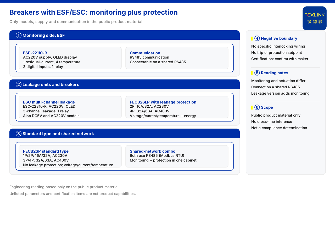
Direct answer
The coordination between a circuit breaker and an electrical fire controller or a multi-channel leakage controller is essentially a division between the "monitoring side" and the "execution side": the monitoring side collects status quantities such as residual current and temperature, while the execution side cuts the circuit when necessary. The product knowledge base records that the electrical fire monitoring & control device (for example ESF-22110-R) uses AC220V with an OLED display and carries 1 residual-current channel, 4 temperature channels, 2 digital inputs, 1 relay output and RS485; the multi-channel leakage controller (for example ESC-22310-R) uses AC220V with an OLED display, 3 leakage-monitoring channels, 1 relay output and RS485; and the intelligent circuit breaker comes in a residual-current variant and a standard variant, both supporting voltage, current and temperature monitoring, energy metering and RS485. The key to coordination is to make clear first who monitors and who acts.
First separate the monitoring side and the execution side
In an electrical fire early-warning chain, the controller and the breaker have different roles. The controller collects status quantities and answers "is there an anomaly"; the breaker handles circuit make-and-break and answers "should the circuit be cut". The knowledge base groups the electrical fire controller and the multi-channel leakage controller as monitoring products and lists the intelligent breaker separately, which corresponds to these two roles.
Once the roles are separated, the approach to coordination becomes clear: on the monitoring side, choose the controller according to the elements to be observed; on the execution side, choose the breaker according to voltage, pole count and whether RCD protection is needed; and connect both to the same network through a shared communication method.
Separating the roles first matters because the two product classes address different questions. The controller focuses on "what has appeared in the circuit", while the breaker focuses on "whether the circuit should be opened". Confusing the two can lead to a controller with nothing to act, or a breaker with nothing to judge from. Coordination presupposes that monitoring and execution each play their own part.
Channel differences among the monitors
The monitoring side also has internal division of labour. The knowledge base records that the electrical fire controller carries 1 residual-current channel, 4 temperature channels, 2 digital inputs, 1 relay output and RS485, while the multi-channel leakage controller (for example ESC-22310-R) uses AC220V with an OLED display, 3 leakage-monitoring channels, 1 relay output and RS485, and the same series has other models for DC5V and AC220V. The difference between them lies in the number of leakage channels and the additional inputs and outputs.
Selection then follows the number of measurement points: when several leakage channels must be monitored at one point, choose the multi-channel leakage controller; when several temperature channels must be observed alongside leakage and digital inputs connected, choose the electrical fire controller. The channel counts differ, but both connect through RS485, and coordinating with a breaker does not change the way the link is accessed.
Breakers split into RCD and standard variants
On the execution side, the intelligent breaker has two clear variants. The knowledge base records that the intelligent breaker with residual-current protection (for example FECB2SLP-2P) includes leakage monitoring and RCD protection, while the standard intelligent breaker (for example FECB2SP-1P) has no RCD. The difference is exactly whether residual-current protection is present.
The knowledge base further gives the model rule: the RCD variant is split by 2P and 4P, with current specifications from 16A to 63A and voltage levels corresponding to AC230V and AC400V; the standard variant is split by 1P, 2P, 3P and 4P, with similar current and voltage tiers. Selection matches pole count, current specification and voltage level to the field circuit, and then decides whether the RCD variant is needed.
From the model arrangement, the RCD variant covers pole counts of 2P and 4P, while the standard variant spans 1P to 4P. This difference shows that whether RCD protection is present affects not only the function but also the available pole counts. If the site needs a 1P or 3P circuit, the standard variant covers it; if RCD protection is needed, it usually falls on a 2P or 4P circuit. Checking the circuit pole count first and then whether RCD is needed avoids repeated rework from a reversed order.
The breaker's own monitored quantities
The breaker is not only an execution element; it also provides monitored quantities itself. The knowledge base records that both the RCD variant and the standard variant support voltage, current and temperature monitoring and energy metering, and both are equipped with RS485. This set of monitored quantities complements the controller's status quantities: the controller leans towards residual current and temperature, while the breaker leans towards voltage, current and energy on the circuit side.
Both provide data over RS485, which means the status quantities of the monitoring side and the execution side can be brought into the same network. Coordination should therefore consider not only the acting relationship but also how these monitored quantities enter platform analysis together.
Shared RS485 network access
The knowledge base records that device downstream supports Modbus RTU (corresponding to RS485), and that the electrical fire controller, the multi-channel leakage controller and both the RCD and standard variants of the intelligent breaker use RS485 communication. This means the three product classes can share one RS485 network access.
The value of shared-network access is that the breaker and the controller need not be networked separately; they exist as nodes on the same network. The coordination relationship can therefore sit on one bus: the monitoring side collects, the execution side acts, and data is shared inside the network.
Using RS485 alike also means that "whether the same downstream protocol is supported" can be a precondition in selection. If a device does not use that communication method, it cannot be merged into the same network and the coordination relationship has to be handled separately. When comparing models, then, communication method should be confirmed alongside function and specification, as important as choosing channel count and pole count.
Monitoring and execution combinations in scenarios
The knowledge base recommends "low-voltage distribution cabinet electrical fire early warning" as a combination of the electrical fire controller, the multi-channel leakage controller, the multi-channel temperature controller and the IoTBox, and recommends "distribution automation three-phase governance" as a combination of the three-phase imbalance monitor and the intelligent breaker with residual-current protection. The former is mainly a monitoring combination; the latter places monitoring and execution in the same combination.
Comparing the two scenarios shows two forms of coordination: where warning is needed, controllers form the network; where governance is needed, a breaker is added for execution. Taken together, coordination between the breaker and the controller can follow one sequence: first separate monitoring and execution; then choose the controller by channel count; choose the breaker by pole count, current, voltage and whether RCD protection is present; and finally confirm that the two share RS485 network access.
The point of this sequence is that it splits function selection and networking conditions into two steps. Function selection decides which products are used, while networking conditions decide whether they can sit on the same network. Only when both are confirmed is coordination between the monitoring side and the execution side complete; confirming only one may still leave a gap at deployment.
Applicability and limits
First, this article explains only the coordination between a circuit breaker and an electrical fire controller or a multi-channel leakage controller; its factual boundary is limited to the product knowledge base, and it introduces no standard clauses, parameters, certifications or cases the knowledge base does not list.
Second, the channel configuration of the electrical fire controller and the multi-channel leakage controller, the pole count, current and voltage specifications and monitored quantities of the RCD and standard variants of the intelligent breaker, the RS485 communication method, and the scenario recommendations are all items listed in the knowledge base; this article does not extend them to other models.
Third, this article does not infer the breaker's actuation logic, trip time or the interlocking sequence with the controller; the relationship between the relay output and circuit make-and-break is limited to the element-function scope listed in the knowledge base.