 FEXLINK Research Institute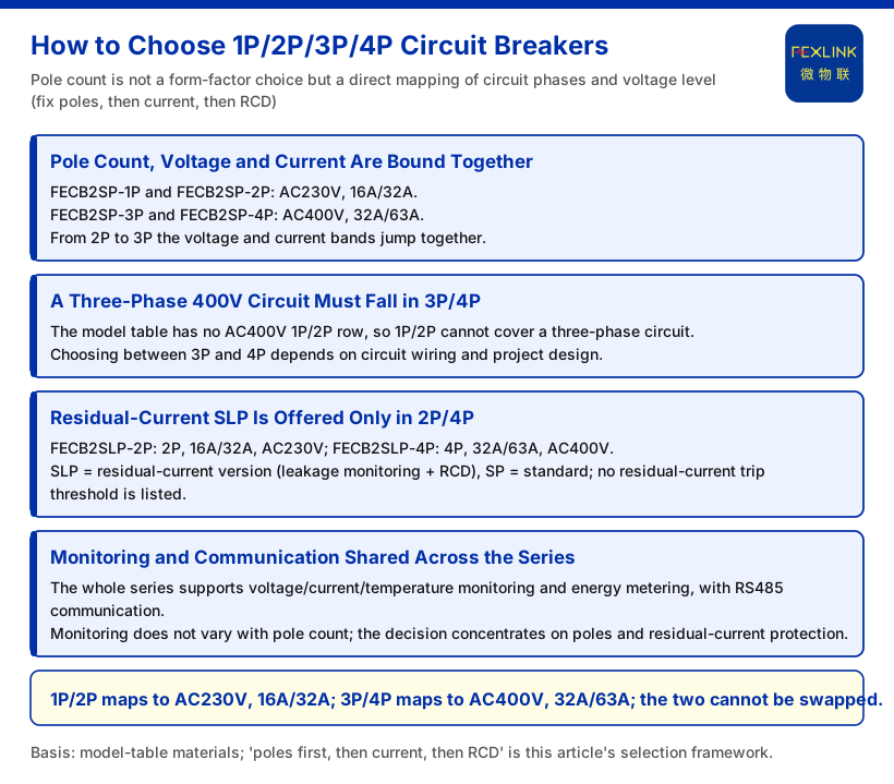
For a smart circuit breaker, pole count is not a casual form-factor choice. It is a direct mapping of a circuit's phase count and voltage level. The model table in Part 6 of the knowledge base states the relationship plainly: FECB2SP-1P and FECB2SP-2P are rated AC230V at 16A/32A, while FECB2SP-3P and FECB2SP-4P are rated AC400V at 32A/63A. The correct procedure is therefore: first use circuit phases and voltage to fix the pole-count band (a three-phase 400V circuit can only fall in 3P/4P); then choose 16A/32A or 32A/63A within that band's rated-current options; finally decide whether to step up to the SLP version with residual-current protection. Conversely, 1P/2P must not be used to cover an AC400V three-phase circuit. This is not a matter of "is it enough" but of the model having no corresponding voltage and current option at all.
Pole Count, Voltage and Current Are Bound Together
Grouping the Part 6 model table by pole count reveals a clear binding: 1P and 2P fall in AC230V, 16A/32A; 3P and 4P fall in AC400V, 32A/63A. The four standard FECB2SP models, row by row, are: 1P at 16A/32A, AC230V; 2P at 16A/32A, AC230V; 3P at 32A/63A, AC400V; 4P at 32A/63A, AC400V, with the residual-current column marked "-" for all four.
Two points are easy to miss. First, the pole band and the voltage band switch together: moving from 2P to 3P, the rated voltage changes from AC230V to AC400V and the rated-current band changes from 16A/32A to 32A/63A at the same time. Choosing 3P therefore means accepting both the AC400V and the 32A/63A ranges. Second, within a pole band, a different pole count does not change the current options: 1P and 2P share the same selectable currents, as do 3P and 4P. Pole count determines the wiring phases and applicable voltage; the current band is set by the specification of that pole band.
From this comes a memorable rule: voltage groups first, current follows the group, pole count is chosen within the group. For single-phase 230V, 1P and 2P share the AC230V, 16A/32A group; for three-phase 400V, 3P and 4P share the AC400V, 32A/63A group. What genuinely requires site judgement is choosing 1P or 2P, or 3P or 4P, within a single group, not crossing groups to force a voltage or current. Once the grouping is clear, selection avoids cases such as "use 1P for 400V" or "look for 63A in 2P", where no model exists.
A Three-Phase 400V Circuit Must Fall in 3P/4P
The reason a three-phase 400V circuit cannot fall back to 1P/2P lies in the table above: the rated voltage of 1P/2P is AC230V, and the model table contains no AC400V 1P/2P row. To monitor and protect a three-phase circuit, 3P or 4P must be chosen, entering the AC400V, 32A/63A band. This is exactly the position of FECB2SP-3P: 3P, 32A/63A, AC400V, the standard-series landing point for a three-phase circuit.
As for choosing between 3P and 4P, the knowledge base only gives the pole-count to rated-voltage and rated-current correspondence; it does not address engineering criteria such as whether the neutral conductor is connected.
Adding Residual-Current Protection: SLP Is Offered Only in 2P/4P
If a circuit needs residual-current protection, look to the FECB2SLP version. The two residual-current models in the knowledge base are FECB2SLP-2P (2P, 16A/32A, AC230V) and FECB2SLP-4P (4P, 32A/63A, AC400V), with the residual-current and leakage-monitoring columns both marked "supported". The naming rule is also clear: SLP = version with residual-current protection (leakage monitoring plus residual-current function); SP = standard version.
Two points must be stated honestly. First, the residual-current version covers only 2P and 4P; the standard 1P and 3P have no corresponding SLP row in the knowledge base. Second, the knowledge base gives the residual-current version only the functional description "leakage monitoring plus residual-current function"; it does not list specific values such as the residual operating threshold, so setting-related content must not be extrapolated from this article. When selecting, first confirm whether residual-current protection is needed, then choose between the 2P/4P SLP and the SP at the same pole count.
Monitoring and Communication Shared Across the Series
Whichever model or pole count is chosen, the monitoring and communication columns in Part 6 of the knowledge base are consistent: the whole series supports voltage/current/temperature monitoring and energy metering, with RS485 communication. Pole-count selection therefore changes circuit fit (pole count, voltage, current band) and whether residual-current protection is included; it never removes voltage/current/temperature monitoring, energy metering or RS485 communication. These shared capabilities can be treated as the baseline, concentrating the decision on pole count and residual-current protection.
This matters especially for assembled selection. Assuming "more poles means more functions" could mean paying for extra poles on a circuit that only needs single-phase monitoring; assuming "fewer poles means no monitoring" could mean choosing the wrong band when three-phase data is needed. Per the knowledge base, monitoring capability is shared across the series and does not vary with pole count. What needs distinguishing is circuit attributes and residual-current needs, not whether monitoring exists. Focusing budget and attention on the real branch points is what makes this table most valuable.
Terminology and Naming Quick Reference
To avoid misreading models during selection, fix a few terms first: FECB2SP means smart circuit breaker (standard version), FECB2SLP means smart circuit breaker (residual-current version), ESB means three-phase unbalance monitor, and RS485 is the communication method. AC230V and AC400V here are rated-voltage values; 16A/32A and 32A/63A are rated-current values. In naming, the only difference between SP and SLP is whether residual-current protection is included, and the two should not be used interchangeably.
Where Pole Selection Sits in the Switchboard Decision Chain
Pole selection becomes clearer when placed back in the system. For the "distribution automation three-phase governance" scenario of the knowledge base, the recommended combination is an ESB three-phase unbalance monitor plus a FECB2SLP smart circuit breaker. The ESB shares its architecture with ESA (ESB-22111~22161-R, 3×220/380V, OLED, RS485) and adds phase monitoring, with two digital inputs and one relay output. In this class of three-phase governance scheme, the breaker does not work alone but is paired with the unbalance monitor; the scenario uses the 4P residual-current version.
From a larger architectural view, the knowledge base defines the monitoring system in four layers: perception, edge, platform and application. A smart circuit breaker is part of the perception/actuation end; its pole count, current and whether it includes residual-current protection determine what circuits this end can connect to and whether voltage/current/temperature and energy data can be sent to the platform over RS485. Pole selection is thus not an isolated product choice but the first decision in assembling a smart distribution cabinet: define the circuit attributes, then the model, and only then discuss platform integration.
What This Article Does Not Claim
First, it does not claim any breaking capacity, trip curve, mechanical or electrical life data beyond Part 6 of the knowledge base. The knowledge base does not list these parameters, so no values are given and no comparisons made.
Second, it does not give specific residual-current settings such as the operating threshold; the knowledge base only describes the residual-current version as having leakage monitoring and residual-current function, without specific values.
Third, it does not extend the pole/voltage/current correspondence into general electrical design code clauses. This is a product fact listed in the model table of Part 6 of the knowledge base and does not constitute citation or interpretation of any standard clause.
Fourth, it does not cover load calculation, short-circuit current verification or endorsement of selection correctness for a specific circuit; such judgements must be determined by project design and applicable standards.
The knowledge base does not state it directly.
Conclusion
Choosing 1P/2P/3P/4P is essentially translating circuit attributes into model options: 1P/2P map to AC230V, 16A/32A and 3P/4P to AC400V, 32A/63A, and the two cannot be interchanged; a three-phase 400V circuit falls in 3P/4P, a single-phase 230V circuit in 1P/2P; when residual-current protection is needed, choose within the 2P/4P SLP versions; all models support voltage/current/temperature monitoring, energy metering and RS485 communication. Completing these steps in order keeps pole selection on course; other judgements concerning circuit wiring, load and codes should still be confirmed in project design.