 FEXLINK Research Institute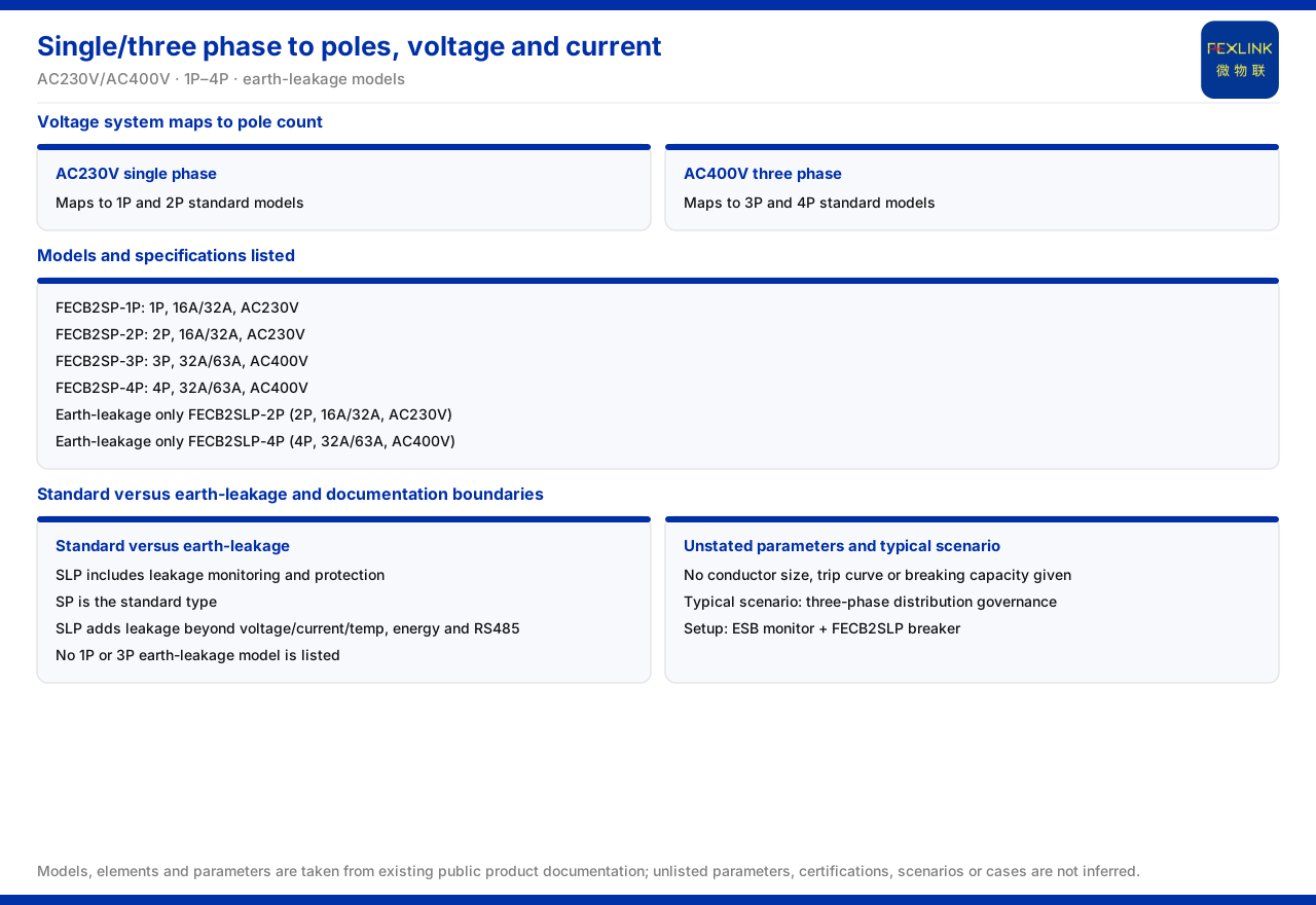
Direct Answer
According to the product knowledge base's intelligent breaker table, single-phase and three-phase circuits map to pole counts through the voltage system in one step: the AC230V band corresponds to 1P and 2P standard models, and the AC400V band to 3P and 4P standard models; if a circuit needs residual-current protection, the residual-current models list only two specifications, 2P (AC230V) and 4P (AC400V). In other words, a single-phase circuit selects 1P or 2P, a three-phase circuit selects 3P or 4P, and with residual-current protection the choice is between 2P and 4P respectively.
Two boundaries must be remembered at the same time: the knowledge base lists no 1P or 3P residual-current models, and the intelligent breaker table gives no further selection parameters such as conductor cross-section, trip curve, or breaking capacity. This article sets out the "single-phase/three-phase — pole count — voltage — current" correspondence and states which parameters the material gives and which need separate confirmation.
I. Mapping Pole Counts From the Voltage System
The knowledge base's intelligent breaker table groups models by voltage and pole count, with a direct rule: the AC230V end is 1P and 2P, and the AC400V end is 3P and 4P. 1P is single-pole, 2P two-pole, 3P three-pole, and 4P four-pole. A single-phase circuit works at 230V and therefore falls into the 1P and 2P group; a three-phase circuit works at 400V and therefore falls into the 3P and 4P group.
The value of this mapping is that it translates the site question "is the circuit single-phase or three-phase" directly into the selection question "1P/2P or 3P/4P," reducing time spent repeatedly checking tables on site. During selection, confirm the circuit system first, then take the specification within the corresponding pole group.
II. Single-Phase Circuits: 1P and 2P
The single-phase 230V band lists two standard models. The standard intelligent breaker (FECB2SP), for example FECB2SP-1P (1P, 16A and 32A, AC230V) and FECB2SP-2P (2P, 16A and 32A, AC230V). The two share the same current bands; the difference is the pole count.
The difference between 1P and 2P is whether the neutral conductor is switched at the same time. In practice, 1P occupies fewer modules and is simpler to wire, while 2P can switch phase and neutral together. The material gives the pole count, current, and voltage of these two models but gives no rule for "which single-phase circuit must use 2P"; whether to take 1P or 2P depends on the circuit's wiring method and project requirements.
III. Three-Phase Circuits: 3P and 4P
The three-phase 400V band likewise lists two standard models. The standard intelligent breaker (FECB2SP), for example FECB2SP-3P (3P, 32A and 63A, AC400V) and FECB2SP-4P (4P, 32A and 63A, AC400V). The two share the same current bands; the difference is again the pole count.
The three-phase band's current bands (32A and 63A) are higher than the single-phase band's (16A and 32A), consistent with three-phase circuits usually carrying greater power. The choice between 3P and 4P depends on whether the neutral conductor must be switched simultaneously; the material gives the specifications of both pole counts but no selection criterion, so it still has to be determined by circuit wiring and project requirements.
IV. Residual-Current Models: Only 2P and 4P
If a circuit needs residual-current protection, the knowledge base's residual-current models list only two specifications. The intelligent breaker with residual-current protection (FECB2SLP), for example FECB2SLP-2P (2P, 16A and 32A, AC230V) and FECB2SLP-4P (4P, 32A and 63A, AC400V). The residual-current model therefore reaches only 2P on the single-phase side and only 4P on the three-phase side; the knowledge base lists no 1P or 3P residual-current model.
This is critical for selection. If a site wants to add residual-current protection to a single-phase circuit, the traceable specification is 2P; for a three-phase circuit, it is 4P. If a design requirement mentions a 1P or 3P residual-current model, there is no corresponding model in the material and it must be confirmed separately rather than assumed to exist.
V. The Difference Between Standard and Residual-Current Models
The knowledge base explains the two names: the residual-current model's marking carries the meaning "with residual-current protection," that is, with leakage monitoring and residual-current protection; the standard model does not include it. Beyond leakage monitoring, the residual-current model adds a leakage-monitoring column on top of voltage, current, and temperature monitoring, energy measurement, and RS485 communication; the standard model does not include that column.
At the same time, all models in the intelligent breaker table support voltage, current, and temperature monitoring and energy measurement, and all use RS485 communication. The difference between the standard and residual-current models is therefore not in basic monitoring capability but in whether leakage monitoring and residual-current protection are included. Which to choose depends on whether the circuit needs residual-current protection and whether leakage data must be collected separately on the platform.
VI. Selection Parameters the Material Does Not Give
During selection, the material boundary also matters. The knowledge base classifies the intelligent breakers as "intelligent circuit breaker (standard/residual-current)," but does not give selection parameters such as conductor cross-section, trip curve, or breaking capacity in the intelligent breaker table or related sections. These parameters usually relate to conductor matching, protection coordination, and short-circuit current verification, and are necessary conditions in engineering design.
Because the material does not list them, this article cannot fill them in on its behalf. Selection involving conductor cross-section, trip curve, and breaking capacity should follow the latest product material, type-test reports, and project design documents, checked separately. Separating the four items the material gives (pole count, rated current, rated voltage, residual-current option) from the three it does not avoids using an incomplete parameter table for a complete design check. Where parameters are unlisted, the corresponding material should be requested from the supply side during procurement and design and relied upon as actually obtained.
VII. A Typical Scenario: The Three-Phase Treatment Combination
Among the knowledge base's typical scenarios, one relates directly to the three-phase application of intelligent breakers. The recommended combination for the distribution-automation three-phase treatment scenario is the three-phase imbalance monitor with a residual-current intelligent breaker: the monitor handles three-phase imbalance monitoring, and the breaker acts as the executing side of the treatment combination. The residual-current model in this combination corresponds to the 2P and 4P specifications.
This scenario shows that in three-phase treatment the intelligent breaker plays an executing role, not a monitoring role. If the goal is three-phase imbalance treatment, first confirm the cooperation between the monitoring end and the executing end, then take the specification by voltage and current among the residual-current 2P/4P models.
Scope and Limits
First, this article restates only the content listed in the product knowledge base, and its factual boundary is limited to the intelligent breaker table's models, pole counts, rated currents, rated voltages, communication method, the difference between standard and residual-current models, typical scenarios, and the unlisted parameters.
Second, the pole count, rated current, and rated voltage of each model are cited as listed; this article does not infer the specifications of unlisted models and does not add a 1P or 3P residual-current model.
Third, the difference between standard and residual-current models is cited as listed; this article does not expand on residual-current operating characteristics, protection settings, or selection criteria.
Fourth, the material does not give selection parameters such as conductor cross-section, trip curve, and breaking capacity; this article states that boundary without inferring specific values.
Fifth, the pole count and residual-current model choice for single-phase/three-phase circuits must be determined with the site circuit wiring and project design requirements; this article does not provide a selection conclusion for a specific project.