 FEXLINK Research Institute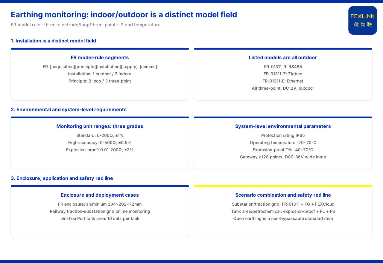
Direct answer
The choice of installation environment for grounding monitoring is already written into the model rule. The product knowledge base specifies that the FR grounding resistance monitor (e.g. FR-01311-R) forms its main body from "signal acquisition, detection principle, installation method, supply", with the communication method listed separately; installation-method code 1 denotes outdoor and 2 denotes indoor. Indoor versus outdoor is therefore not a matter of installation habit but an independent selection item at the model level. The three listed types of the grounding resistance monitor — FR-01311-R, FR-01311-Z and FR-01311-E — all have an outdoor installation environment, a three-electrode measurement method, DC12V supply, and RS485, Zigbee and Ethernet communication respectively. The environment choice must also be checked together with grounding-grid conditions, explosion-proof requirements, and the system-level protection rating and operating temperature, so that "where it is installed" and "how it stays installed" are both made clear.
The installation method is an independent field in the model
The model rule the product knowledge base gives for the FR grounding resistance monitor is: the main body consists of signal acquisition, detection principle, installation method and supply, with the communication method listed separately. Installation-method code 1 corresponds to outdoor and 2 to indoor. Putting the installation method into the model body means it is as important in selection as signal acquisition, detection principle and supply, rather than being decided casually at the installation stage. The benefit is that the indoor and outdoor forms are distinguished at ordering time, so the site will not pick a mismatched form because one environmental condition was omitted.
Outdoor form: enclosure and on-site adaptability
The product knowledge base notes that the FR grounding resistance monitor has an aluminium enclosure of 204×202×72 mm. The aluminium enclosure together with the outdoor installation method corresponds to the need for grounding-grid monitoring that is exposed to the outdoor environment for long periods. The product knowledge base also records that the FR and FRP series grounding resistance monitors have been applied to projects such as online grounding-grid monitoring of railway traction substations and the Jinzhou Port oil-tank area (10 sets per tank). These two applications show that the outdoor form is not a laboratory condition but an on-site form that must withstand the outdoor environment and continuous operation; when the monitored grounding grid is located outdoors, the outdoor installation method should therefore be chosen explicitly at the model level.
Different grounding-grid conditions: range and accuracy types
Beyond the installation environment, the measurement conditions of the grounding grid itself also affect model choice. The system-level reference parameters for the grounding resistance monitoring system list three classes of monitoring unit: the standard type of 0 to 200 Ω at ±1% accuracy; the high-precision type of 0 to 500 Ω at ±0.5%; and the explosion-proof type of 0.01 to 200 Ω at ±2%. Range and accuracy are distinguished by the measured object and the installation environment, showing that "where it is installed" and "how accurately it must measure" need to be considered together. For the same grounding grid, the high-precision type can be chosen for higher accuracy, and the explosion-proof type must be chosen when in an explosion-proof area; the way the three are typed is itself part of environmental adaptation.
A dedicated type for explosion-proof environments
When the monitoring point is in an explosion-proof area such as an oil-tank area or petrochemical site, the 0.01 to 200 Ω explosion-proof monitoring unit given by the product knowledge base is marked with explosion-proof rating Ex d IIB T4/T6 Gb. This rating is the direct basis for selection in an explosion-proof environment. In its typical scenarios the product knowledge base also states clearly that oil-tank-area and petrochemical lightning-protection and explosion-proof scenarios recommend explosion-proof grounding resistance monitoring, combined with the FL lightning current / transient current monitor and the FS surge protective device monitor. The choice of installation environment in an explosion-proof environment is therefore not only "indoor or outdoor"; the explosion-proof type must also be selected at the model level, otherwise the monitoring unit itself may not be able to enter the area.
System-level environmental requirements: protection rating and temperature
The installation environment also needs to be checked at the system level. The product knowledge base gives system-level environmental parameters: protection rating IP65, operating temperature -20 to 70 °C, and -40 to 70 °C for the explosion-proof T6 version; the smart gateway mounts no fewer than 128 points and supports cascading, has no fewer than 4 RS485 channels and no fewer than 2 Ethernet ports, with 4G, 5G and LoRa optional, buffers no fewer than 15 days of data, is powered by a wide DC9 to 36V range, and is itself IP65. These parameters show that beyond indoor and outdoor, the protection rating and temperature range should also be checked as deployment-environment items: only when the ratings and temperature intervals of the monitoring unit, the gateway and the site environment match one another is the choice of installation environment complete.
Confirming the installation environment by scenario
Applying the clues above to scenarios, the product knowledge base gives two examples. For online grounding-grid monitoring of substations and traction substations, it recommends the grounding resistance monitor represented by FR-01311 (one set per point) together with the FG lightning-protection smart gateway and the FEXCloud IoT cloud platform; for oil-tank-area and petrochemical explosion-proof scenarios, it recommends explosion-proof grounding resistance monitoring combined with the FL lightning current / transient current monitor and the FS surge protective device monitor. The difference between the two lies in the installation environment: the former targets an outdoor grounding grid, while the latter additionally requires the explosion-proof type. Confirming the installation environment by scenario answers "which environmental form this class of monitored object should adopt", rather than applying one fixed installation method.
Checking sequence
Gathering the choice of installation environment into a sequence, four steps can be followed. First, confirm whether the monitoring point is indoors or outdoors, and select the installation method in the model body accordingly. Second, choose the range and accuracy type by the grounding-grid condition, taking the high-precision type when higher accuracy is needed. Third, judge whether it is in an explosion-proof area, and select the explosion-proof type and its rating when needed. Fourth, return to the system level to check the protection rating and operating temperature, confirming that the rating intervals of the monitoring unit and the gateway agree with the site. In this order, the installation environment answers "how form, type and environmental rating align".
Applicability and limits
First, this article only restates content listed in the product knowledge base; its factual boundary is limited to the FR grounding resistance monitor's model rule, installation-method and detection-principle codes, the installation environment and communication listed in the model table, the external dimensions, the application scenarios, and the range/accuracy typing and environmental parameters of the grounding resistance monitoring system, and it introduces no unlisted parameters, certifications or cases.
Second, the FR grounding resistance monitor's model rule, installation-method codes and detection-principle codes are cited on the terms listed in the product knowledge base; this article makes no judgement on the installation conclusion of a specific project.
Third, the outdoor installation, three-electrode method and supply/communication configuration of the grounding resistance monitor models FR-01311-R, FR-01311-Z and FR-01311-E listed in the model table, and the external dimensions, are all cited on the terms listed in the product knowledge base.
Fourth, the monitoring unit's range, accuracy and explosion-proof rating, as well as the protection rating, operating temperature, gateway mounting and supply parameters of the grounding resistance monitoring system, are all cited on the terms listed in the product knowledge base; this article does not infer unlisted configurations from them.
Fifth, the red line for abnormal open circuit of grounding resistance is based on GB 50057 and is a non-bypassable item listed in the product knowledge base; this article draws no conclusion on the criterion value or number of points for a specific project.
Sixth, this article does not commit to any specific project's selection result or on-site performance, which remain subject to the latest product documentation and project scheme.