 微物联研究院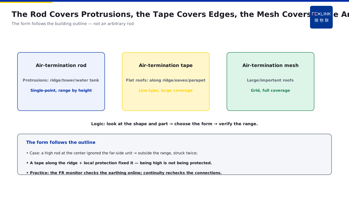
Direct Answer
Should the roof use a rod, a tape, or a mesh? The answer: the air-termination form follows the building outline — protruding parts (roof ridges, tower tops) use air-termination rods, flat roofs use air-termination tapes along the edges, and large or important roofs use air-termination meshes. The protection range is verified by the rolling-sphere method (taking the sphere radius by the lightning-protection class), ensuring protected objects do not fall outside the range — it is not "the higher the rod, the better".
At a plant, a high rod was erected at the center of the roof following a drawing, ignoring a large roof-mounted unit on the far side of the ridge: by the rolling-sphere calculation, that unit lay outside the protection range, and it was struck twice in the storm season. After adding a tape along the ridge plus local protection for the unit, the problem disappeared. The key distinction: air termination is not "the higher, the better" — the form is chosen by the building shape (rod/tape/mesh), the range is verified by the rolling sphere, and misses usually come from "copying the drawing without looking at the shape".
Why:
- Three forms: the rod covers protrusions, the tape covers flat edges, the mesh covers large areas;
- The rolling sphere: the radius is taken by the lightning-protection class;
- Protected objects: must lie within the protection range;
- Special treatment: protrusions/antennas/PV panels are verified separately.
Key insight: "Choose the air-termination form by the building outline and verify the range by the rolling sphere — being high does not mean being protected; misses come from ignoring the shape."
At a park, solar panels were added to the roof without re-verifying the air-termination coverage, and a strike damaged several modules. After re-calculating the rolling-sphere range for the panel positions and adding tapes, the damage did not recur. Lesson: adding roof protrusions (PV/antennas) requires re-verifying the protection range — the old scheme does not automatically cover new objects.
1. The Applicable Parts of the Three Air-Termination Forms
Step one: where the rod, tape and mesh go.
Air-termination rod (mast):
- For protruding parts: roof ridges, tower tops, water towers;
- Single-point protection; the coverage is set by the height;
- Priority on the highest protrusions;
- Free-standing masts also work.
Air-termination tape:
- For flat roofs: along ridges, eaves, parapets;
- Laid along edges; line-type protection;
- Large coverage, fitting the building;
- The most common roof form.
Air-termination mesh:
- For large/important roofs;
- Laid in a grid; full coverage;
- The mesh size follows the class;
- For important buildings/special places.
Key insight: "The rod covers protrusions, the tape covers edges, the mesh covers large areas — the form follows the building outline, not an arbitrary rod."
2. The Rolling-Sphere Method and the Radius by Class
Step two: how the protection range is calculated.
The rolling-sphere principle:
- A sphere of the rolling radius rolls along the ground;
- It is tangent to the air terminations and the ground;
- The zone inside the sphere is the protection range;
- The untouched zone is the blind area.
The radius by class:
- Class I: rolling radius 30 m;
- Class II: 45 m;
- Class III: 60 m;
- The higher the class, the smaller the radius, the stricter the protection.
The effect of the value:
- A smaller radius → a narrower range;
- Class I is the strictest;
- The higher the rod, the wider the single coverage but the easier to miss at the edges;
- Taking the radius by class is key.
Key insight: "The rolling sphere rolls along the ground and cuts out the protection range — the radius follows the class (I: 30 m, II: 45 m, III: 60 m); a higher class means stricter protection."
3. How Protected Objects Fall within the Range
Step three: how to confirm the protection holds.
The calculation steps:
- Determine the building's class (connecting to KD-0179);
- Take the corresponding rolling radius;
- Roll the sphere along the building outline;
- See whether the protected object is inside.
Common misses:
- A protrusion outside the rod's range;
- No tape at the roof edges;
- Too large a mesh on a big roof;
- New objects not re-verified.
How to confirm:
- Calculate by the range diagram;
- Check every protected object point by point;
- Add air terminations where there are blind zones;
- Double-verify with software/diagrams.
Key insight: "Every protected object must lie inside the sphere — check point by point and add where there are blind zones; 'roughly within range' is where misses happen."
4. Special Treatment of Protrusions, Antennas and Solar Panels
Step four: what to do about new things on the roof.
Types of protrusions:
- Antennas/lightning arresters/exhaust pipes;
- Solar panels/PV supports;
- Cooling towers/water tanks/decorations;
- Protrusions higher than the tape.
The treatment principles:
- Higher than the tape → add separate protection;
- Solar panels are conductors → bring them into the air-termination system;
- Antennas need side-flash/equipotential protection;
- New protrusions must be re-verified.
Common errors:
- Adding PV without re-verifying the range;
- Protruding metal not connected to the down-conductor;
- Insufficient clearance between antennas and the tape;
- Believing "a rod on the roof covers everything".
Key insight: "New roof protrusions (PV/antennas) must be re-verified and brought into the system — the old protection range does not automatically cover new objects."
5. The Connection Requirements between Air Terminations and Down-Conductors
Step five: the air-termination → down-conductor → earthing chain.
Connection requirements:
- Reliable connection between the air terminations and the down-conductors;
- Multiple down-conductors for shunting (connecting to KD-0182);
- Welded/mechanical reliability at the joints;
- Electrical continuity and low impedance.
Counterattack prevention:
- Keep the clearance between the down-conductors and protected objects;
- Use equipotential bonding when it cannot be met;
- The down-conductor potential is high when carrying current;
- The whole system is continuously connected.
Practice verification:
- Verify the connections by continuity testing;
- Monitor online with the FR Earth-Resistance Monitor;
- Recheck the connections after strikes;
- Repair abnormalities in time.
Key insight: "Air termination → down-conductor → earthing is one chain — reliable connection, electrical continuity, measurable continuity; a break in any link makes it all useless."
6. Product Implementation: Air Termination and Earthing as One
WeiWuLian products manage the air-termination system:
- FR Earth-Resistance Monitor: online monitoring of the earthing system;
- Continuity recheck: verifying the air-termination-down-conductor-earthing connections;
- Strike-event correlation: rechecking the system after strikes;
- Data loop: digitizing the range and the state.
The design principle in one sentence: "Form by the outline, range by the rolling sphere, connection by continuity — close the three and manage the air-termination system with data."
7. Common Misjudgments
- "The higher, the better": ignoring edge misses. Result: a protrusion outside the protection. Correct: choose the form by the shape and verify by the rolling sphere.
- "Copy the rod from the drawing": ignoring the building shape. Result: misses/waste. Correct: choose rod/tape/mesh by the outline.
- "Take any radius": ignoring the class. Result: insufficient protection. Correct: take the radius by the class.
- "No need to recheck after adding PV": ignoring new objects. Result: damaged modules. Correct: re-verify and add protection.
- "Connect it loosely": ignoring electrical continuity. Result: a broken chain, failed protection. Correct: verify by continuity testing.
Scope and Limitations
This article explains the applicable parts of the three air-termination forms (rod/tape/mesh), rolling-sphere range calculation, protected-object confirmation, special treatment of protrusions, and the connection requirements with down-conductors, applicable to air-termination selection and range calculation. The exact rolling radii and layouts follow GB 50057-2010 and its revisions; this article explains only the selection logic and calculation method. All cases are anonymized (a plant, a park) and do not refer to any specific customer.