 微物联研究院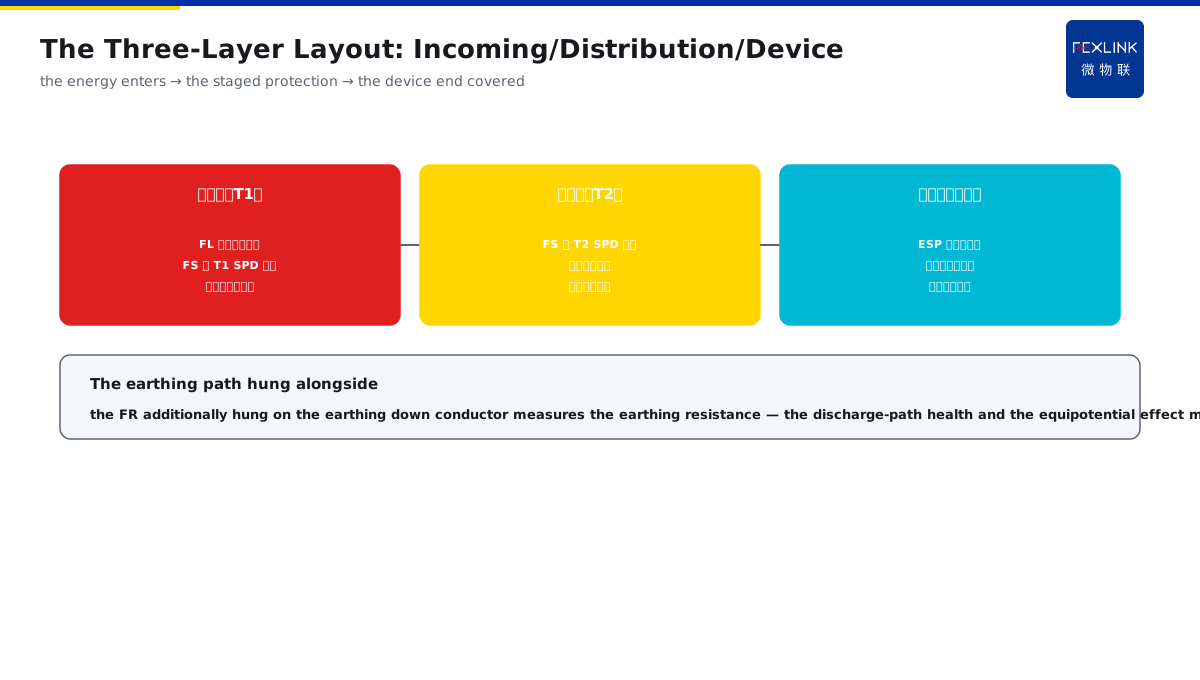
Direct Answer
With the LPZ zoning approach in mind, what should the lightning-protection monitoring products be installed at each zone boundary? The answer: lay out the points by the zone boundary — at the LPZ0/1 incoming boundary, install the FL lightning-current monitor plus the FS/ESM to monitor the T1 SPD; at the LPZ1/2 sub-distribution, install the FS to monitor the T2 SPD status and leakage; on the earthing down conductor, install the FR to monitor the earthing resistance; at the sensitive-device end, use the ESP neutral-ground voltage to fill the blind spot; the zoning approach makes the monitoring points correspond one-to-one with the weak protection boundaries.
At a park, monitoring was originally installed on every distribution branch, with the points evenly scattered, the cost high and the key boundaries missed; after the re-layout by the LPZ zoning: the FL+FS at the incoming boundary monitoring the T1 SPD, the FS at the sub-distribution monitoring the T2 SPD, the FR on the earthing down conductor monitoring the earthing resistance, and the ESP at the device end filling the blind spot — the points were reduced from 20 to 8, with the key boundaries fully covered, and the data review after one strike was complete. The key distinction: the layout is not the even scattering of the pepper — the monitoring points should be hung at the protection-zone boundaries: the LPZ0/1 incoming with the FL+FS (the lightning current + the T1 SPD), the LPZ1/2 sub-distribution with the FS (the T2 SPD), the earthing down conductor with the FR, and the device end with the ESP to fill the blind spot — the points correspond one-to-one with the weak protection boundaries.
Why:
- The incoming boundary: the FL measures the lightning current + the FS measures the T1 SPD;
- The distribution boundary: the FS measures the T2 SPD status and leakage;
- The earthing path: the FR measures the earthing resistance;
- The device end: the ESP measures the neutral-ground voltage to fill the blind spot.
Key insight: "The layout follows the zone boundary — the LPZ0/1 incoming with the FL+FS (the lightning current + the T1 SPD), the LPZ1/2 sub-distribution with the FS (the T2 SPD), the earthing down conductor with the FR, and the device end with the ESP to fill the blind spot — the monitoring points correspond one-to-one with the weak protection boundaries, few but precise."
At a data center, the monitoring points were scattered at 30 places, and after the strike the key data was missing — the incoming SPD operation count was not recorded, and the earthing-resistance change was not measured. After converging to 10 places by the LPZ zoning, the incoming/distribution/earthing/device end all had the data, and one strike review located everything completely. Lesson: the pepper-scattering layout is a waste — lay out by the zone boundary, with few points and the key boundaries fully covered, and the data has value.
Overview: run "what each LPZ boundary installs → how the three layers of the incoming/distribution/device end are laid out → how the earthing and the equipotential are hung → how the layout corresponds to the SPD grading" as one monitoring-layout cognition. Lay out the points by the zone boundary: at the LPZ0/1 incoming boundary, install the FL lightning-current monitor plus the FS/ESM to monitor the T1 SPD; at the LPZ1/2 sub-distribution, install the FS to monitor the T2 SPD status and leakage; on the earthing down conductor, install the FR to monitor the earthing resistance; at the sensitive-device end, use the ESP neutral-ground voltage to fill the blind spot. The four layers are unfolded below.
A "sentry deployment" analogy: think of the LPZ zoning layout as deploying the sentries along the defense line. The defense line (the LPZ boundaries) is the pass where the lightning current is weakened stage by stage: the first pass (LPZ0/1 incoming) is the "city gate", where you must see how many enemies (the lightning current) come in and whether the garrison (the T1 SPD) blocked them — install the FL (seeing how much came) plus the FS (watching the garrison status); the second pass (LPZ1/2 sub-distribution) is the "inner city", watching whether the T2 SPD garrison leaks; the last pass (the device end) is the "accounting room", using the ESP to see whether there is "seepage" (the neutral-ground voltage). The sentries are not the more, the better — every key pass must be watched; the pepper scattering sets up sentries everywhere but misses the passes, while the boundary layout keeps the passes guarded, few but precise. The sentry analogy: the LPZ boundaries = the defense-line passes, the incoming FL+FS sees the lightning current and the T1 SPD, the sub-distribution FS sees the T2 SPD, and the device end ESP sees the seepage — the passes guarded, few but precise.
1. The LPZ Boundaries: What to Install
Step one: first look at the recommended monitoring products at each LPZ boundary.
The LPZ0/1 incoming boundary:
- The FL lightning-current monitor;
- The FS/ESM monitoring the T1 SPD;
- Recording the entering lightning energy;
- The first-pass observation of the incoming protection.
The LPZ1/2 distribution boundary:
- The FS monitoring the T2 SPD;
- Monitoring the operation and the leakage;
- The residual-voltage coordination verified;
- The distribution-layer protection observed.
The device end (sensitive):
- The ESP neutral-ground voltage filling the blind spot;
- Monitoring the equipotential effect;
- The end residual voltage verified;
- The device-side blind area covered.
Key insight: "Each boundary installs the corresponding product — the incoming with the FL+FS (the lightning current + the T1 SPD), the sub-distribution with the FS (the T2 SPD), and the device end with the ESP (the neutral-ground voltage filling the blind spot); each layer's monitoring corresponds to this layer's weak protection point."
2. The Three-Layer Layout: Incoming/Distribution/Device End
Step two: the three-layer monitoring layout of the incoming T1, the distribution T2 and the device end.
The incoming layer (T1):
- The FL measuring the entering lightning current;
- The FS measuring the T1 SPD operation;
- Judging whether the main discharge is in place;
- The energy-level recording.
The distribution layer (T2):
- The FS measuring the T2 SPD status;
- The leakage reflecting the degradation;
- The residual-voltage coordination verified;
- The mid-level protection observed.
The device layer (the end):
- The ESP measuring the neutral-ground voltage;
- Reflecting the equipotential effect;
- The end blind spot filled;
- The final device-safety verification.
Key insight: "The three-layer layout is complete — the incoming layer measures the lightning current and the T1 SPD, the distribution layer measures the T2 SPD status and leakage, and the device layer uses the ESP to fill the blind spot — from the energy entering, the staged protection to the device end fully covered."
3. The Earthing and the Equipotential: How to Hang Them at the Boundaries
Step three: how the earthing and the equipotential monitoring points are hung at the zone boundaries.
The earthing down conductor:
- The FR measuring the earthing resistance;
- Reflecting the discharge-path health;
- The earthing degradation found early;
- Hung on the earthing path.
The equipotential effect:
- The ESP measuring the neutral-ground voltage;
- Reflecting the equipotential completeness;
- The bonding degradation identified;
- Hung at the sensitive-device end.
The hanging principle:
- Hanging along the current path;
- Measuring the weak boundaries;
- The earthing and the equipotential both important;
- The data mutually verifying.
Key insight: "The earthing and the equipotential hanging — the FR hung on the earthing down conductor measures the earthing resistance reflecting the discharge-path health, and the ESP hung at the device end measures the neutral-ground voltage reflecting the equipotential completeness; hang along the current path, measure the weak boundaries, and let the data verify mutually."
4. The Layout and the Grading: How They Correspond
Step four: the correspondence between the monitoring layout and the SPD grading.
The T1 correspondence:
- The T1 SPD at the incoming boundary;
- The FL+FS monitoring correspondingly;
- The discharge energy recorded;
- The first layer of the staged protection.
The T2 correspondence:
- The T2 SPD at the sub-distribution;
- The FS monitoring correspondingly;
- The residual-voltage coordination verified;
- The second layer of the staged protection.
The device-end correspondence:
- The end fine protection;
- The ESP filling the blind spot for the verification;
- The coordination criterion checked;
- The end of the staged protection.
Key insight: "The layout corresponds to the grading — the T1 incoming with the FL+FS, the T2 sub-distribution with the FS, and the device end with the ESP filling the blind spot; every protection-grade boundary has the corresponding monitoring, and the staged protection is verifiable."
5. Product Implementation: From the Layout to the Solution
WeiWuLian products bring the zoning layout to the complete solution:
- FL lightning-current monitor: the energy recording at the incoming boundary;
- FS SPD monitor: the T1/T2 SPD status and leakage;
- FR earthing-resistance monitor: the earthing-path health;
- ESP neutral-ground-voltage monitor: the equipotential filling at the device end;
- FG intelligent lightning-protection gateway: the data aggregation and the warning.
The design principle in one sentence: "The layout follows the boundary and the data forms the loop — the FL/FS/FR/ESP are laid out along the LPZ boundaries, the FG gateway aggregates the data, and the staged protection is verifiable throughout."
6. Common Understanding Misjudgments
- "The more the points, the better": wrong. Lay out by the zone boundary, few but precise.
- "Only the SPD, no monitoring": wrong. The monitoring verifies whether the protection is in place.
- "Only the lightning current": wrong. The earthing, the equipotential and the SPD status must all be measured.
- "The layout unrelated to the grading": wrong. The T1/T2/device end each has the corresponding product.
- "The data uncollected and unused": wrong. The data aggregation and the review form the loop improvement.
Scope and Limitations
This article explains the lightning-protection online monitoring layout by the LPZ zoning (the boundary products, the three-layer layout, the earthing hanging, and the grading correspondence), applicable to the monitoring-solution design and the point planning. The specific selection and the zoning follow GB 50343-2012 and the product manuals; this article explains only the layout logic. All cases are anonymized (a park/a data center) and do not refer to any specific customer.