 FEXLINK Research Institute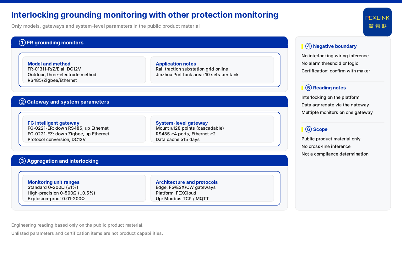
Direct answer
The linkage between a grounding monitoring system and other lightning-protection monitoring relies on the gateway layer: the grounding state quantity is acquired at the perception layer, gathered through the lightning-protection smart gateway, and then sent uplink to the platform under a unified communication protocol, to be compared in one place with the monitoring data of surge protective devices and lightning current. The product knowledge base records that the grounding resistance monitor (such as FR-01311-R) is DC12V supplied, outdoor-mounted and three-pole-method measured, with communication selectable among RS485, Zigbee and Ethernet; the lightning-protection smart gateway is of protocol-conversion type, with RS485 or Zigbee downlink and Ethernet uplink; the system-level smart gateway supports mounting no fewer than 128 points and offers optional 4G, 5G or LoRa uplink. Only by putting the grounding state into this chain does the linkage have a common landing point.
1. What state quantities grounding monitoring itself provides
The grounding state quantity comes from the grounding resistance monitor. The product knowledge base records that the models of this series are all DC12V supplied, outdoor-mounted and three-pole-method measured, with communication selectable among RS485, Zigbee and Ethernet. Three-pole-method measurement and outdoor mounting show it faces long-term online monitoring of an on-site earth grid rather than temporary measurement.
This product positioning decides that the grounding state quantity can be obtained continuously. Unlike a one-off acceptance measurement that leaves a single record point, it brings the grounding state into daily observation and can therefore be aligned on a time axis with other monitoring data. This is the premise on which the linkage can hold.
From the communication options, the series offers RS485, Zigbee and Ethernet downlink, showing that the grounding resistance monitor itself can adapt to both wired and wireless on-site wiring conditions. Which downlink to choose depends on the distance between the site and the gateway and on the available wiring resources; whichever is chosen, the state quantity must first enter the gateway, so the first leg of the linkage always points to the same layer.
2. Range levels decide the applicable boundary
The range of a grounding monitoring unit is not a single level. The product knowledge base lists three: the standard type 0-200 Ω with an accuracy of plus or minus 1%; the high-accuracy type 0-500 Ω with an accuracy of plus or minus 0.5%; and the explosion-proof type 0.01-200 Ω with an accuracy of plus or minus 2% and an explosion-proof rating of Ex d IIB T4/T6 Gb. The three correspond to different measurement ranges and installation environments, showing that the grounding state quantity has different readable intervals in different scenarios.
Reading range together with accuracy shows whether a level supports a site judgment. The range levels also suggest that when grounding monitoring links with other monitoring, the state quantities at both ends must fall within comparable intervals for the linked analysis to be meaningful.
The three range levels correspond to three different landing points: the standard type faces a conventional earth grid, the high-accuracy type faces occasions with a higher demand on reading resolution, and the explosion-proof type faces restrictive environments. The change of accuracy from plus or minus 1% to plus or minus 0.5% and then to plus or minus 2% shows that range and accuracy do not vary in the same direction, so selection should look not only at how wide the range is but also at whether the accuracy meets the resolution a judgment needs.
3. The gateway is the hub of linkage
For grounding monitoring to link with other lightning-protection monitoring, a layer of protocol conversion and gathering is needed in between. The product knowledge base records that the lightning-protection smart gateway is of protocol-conversion type and DC12V supplied: one model has RS485 downlink and Ethernet uplink, another Zigbee downlink and Ethernet uplink. In this way the grounding downlink interface and the uplink network interface are separated, and front-end devices can choose the downlink method by on-site wiring conditions.
The hub role of the gateway is to converge different downlink methods onto a unified uplink. The grounding monitor can take RS485, Zigbee or Ethernet, and the gateway offers exactly the RS485 and Zigbee downlinks, which correspond. The linkage is therefore not about devices interconnecting directly but about gathering state quantities through the gateway and reporting them uplink in a unified way.
4. System-level parameters support multi-type data aggregation
When the number of monitoring points grows, the gateway's capability is measured by system-level parameters. The product knowledge base records that the smart gateway of the grounding resistance monitoring system supports mounting no fewer than 128 points and can cascade, with no fewer than 4 RS485 ports and no fewer than 2 Ethernet ports, optional 4G/5G/LoRa, data buffering no fewer than 15 days, and DC9-36V wide voltage with IP65. These parameters decide how many points the system can access, how long it can buffer and under what supply and protection conditions it can run.
Multi-port access and local buffering are especially key to the linkage: multi-port access means one gateway can carry grounding and other monitoring at once, and local buffering retains data when the link breaks, so state quantities are not lost in the linkage chain.
Wide-voltage supply and IP65 decide where the gateway itself can be deployed. A DC9-36V input range means the gateway can work under various DC supply conditions, and IP65 means it can be installed in outdoor conditions. When a grounding monitoring point is outdoors or in the field, whether the gateway can be deployed nearby directly affects the length of the downlink and the amount of on-site work. System-level parameters are therefore not just the gateway's own specifications but also determine the topology of the linkage chain.
5. The protocol matrix is the common language of linkage
For different monitoring data to gather in one place, a common communication language is required. The product knowledge base records that device uplink supports Modbus TCP and MQTT, can run over Ethernet and 4G, and offers optional gateway-level IEC 61850. This means the grounding state quantity and the state quantities of surge protective devices and lightning current can be reported uplink in a unified way at the gateway side.
In the four-layer architecture, the edge layer, borne by gateway devices such as the lightning-protection smart gateway and related edge components, handles protocol conversion, edge computing and local buffering, while the platform layer handles device access and the time-series database. The linkage of grounding monitoring with other monitoring is precisely gathered at the edge layer and compared at the platform layer.
6. Linkage forms in a landing scenario
The product knowledge base lists online monitoring of substation and traction-substation earth grids as a typical application scenario, with a recommended combination of the grounding resistance monitor (one set per point), the lightning-protection smart gateway and the IoT cloud platform. This combination shows that earth-grid monitoring is itself a complete chain from perception to platform, along which the grounding state quantity enters the platform.
A companion application note also records that the grounding resistance monitor has been applied to online earth-grid monitoring of a railway traction substation and to the oil-tank farm of Jinzhou Port (10 sets per tank). The common point of these scenarios is that the monitoring points are scattered and need to be online for the long term, exactly matching the value of the gateway's multi-port access and local buffering. Placing grounding into this system lands the linkage between grounding monitoring and other lightning-protection monitoring in a concrete form.
Scope and limitations
First, this article only explains the linkage between a grounding monitoring system and other lightning-protection monitoring; its factual boundary is limited to the product knowledge base, and it introduces no standard clause, parameter, certification or case not listed there.
Second, the supply, installation method, measurement method and communication options of the grounding resistance monitor, the downlink and uplink configuration of the lightning-protection smart gateway, the mounting points, interface counts, buffering and supply and protection parameters of the system-level smart gateway, the three range levels and accuracies of the grounding monitoring unit, and the description of the four-layer architecture and protocol matrix are all content listed in the product knowledge base; this article does not extend them to other models.
Third, the project names in the application note are used only to illustrate scenario types and do not constitute an inference about project scale, effect or delivery scope.