 FEXLINK Research Institute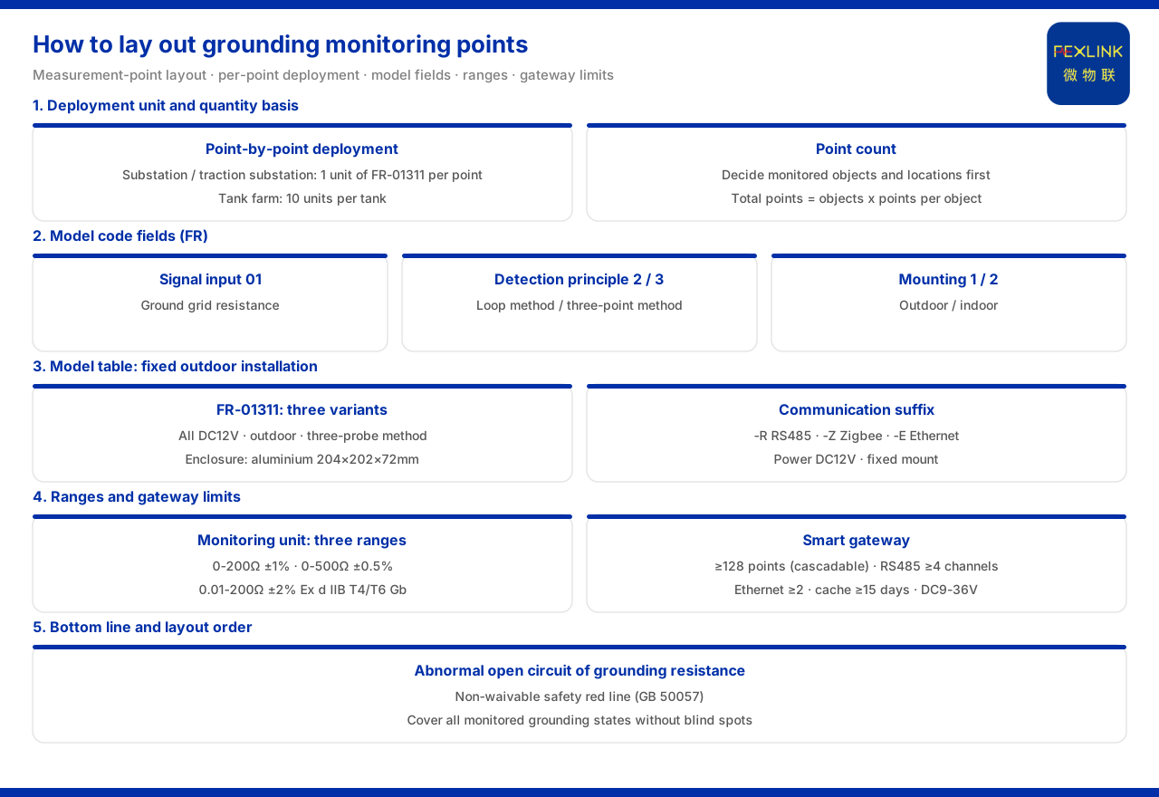
Direct answer
The deployment unit of grounding-grid online monitoring is the "point," not the whole grid. The product knowledge base gives the combination, in its typical scenarios, as: for online monitoring of substation and traction-substation grounding grids, one set of grounding resistance monitor (FR-01311) at each grounding point, aggregated by a gateway to the cloud platform; in project records, the Jinzhou Port oil-tank farm is configured at 10 sets per tank. Siting and selection therefore require checking four classes of information. First, the model rule: the body segment is composed of signal acquisition, detection principle, installation mode and power supply, with communication listed separately; signal acquisition 01 is grid resistance, detection principle 2 is the loop method and 3 the three-point method, and installation mode 1 is outdoor and 2 indoor. Second, in the model table the three types of grounding resistance monitor (FR-01311-R/Z/E) are all DC12V-supplied, outdoor-installed and three-pole-method measured, with communication of RS485, Zigbee and Ethernet respectively, and an aluminum housing of 204×202×72mm. Third, the system-level monitoring unit has standard, high-precision and explosion-proof grades, chosen before siting by field range and environment. Fourth, the upper limit of point scale is constrained by the gateway's mounting and interface capability. The safety red-line guard also lists "abnormal open circuit of grounding resistance" as an unbypassable safety red line, based on GB 50057.
1. Deployment unit: why it is counted by "point"
A grounding grid is an integral whole, but online monitoring does not sample at only one place. The typical scenarios write the recommendation as "one set of FR-01311 per point plus a gateway plus the cloud platform," showing that monitoring points correspond one-to-one with monitored locations: wherever the state of a grounding location must be observed, one set of grounding resistance monitor is deployed there. Project records confirm this—the Jinzhou Port oil-tank farm is configured at 10 sets per tank, so the number of points corresponds to the number of protected objects (tanks). The first step is therefore to fix what a "point" is: a point is a grounding location or protected object needing continuous observation, not a vague single number for the whole grid.
2. Model rule: writing the measured object into the fields
The model rule encodes the information needed for selection directly into the model fields. The body segment is composed of signal acquisition, detection principle, installation mode and power supply, with communication listed separately; signal acquisition 01 means grid resistance, that is, the series acquires the resistance of the grounding grid; the detection principle has two grades, 2 for the loop method and 3 for the three-point method; and installation mode 1 is outdoor and 2 indoor. Online monitoring is therefore not vaguely "measuring grounding," but writes the measured physical quantity, measuring principle and installation environment item by item into the model. During selection, aligning the field's measured object, measuring method and installation location with these field groups determines the model composition.
3. The outdoor fixed-installation form in the model table
The model table explains the actual form. Three types of grounding resistance monitor (FR-01311-R/Z/E) are listed; all three are DC12V-supplied, outdoor-installed and measured by the three-pole method, differing only in communication, which is RS485, Zigbee and Ethernet respectively; the housing is an aluminum shell of 204×202×72mm. This is a fixed-installation device requiring power supply, an installation location and a communication mode, not a hand-held spot-check tool. Point conditions can therefore be judged: every monitoring point needs a fixable installation location, an available power supply and a usable communication path.
4. Point density: from typical scenarios to project records
The number of points is determined by the scale of the monitored objects. The typical scenarios give the substation and traction-substation combination as one set of FR-01311 per point plus a gateway and the cloud platform; project records show the series applied to railway traction-substation grounding-grid monitoring, and to 10 sets per tank at the Jinzhou Port oil-tank farm. Both point to the same organization: first determine the grounding locations or protected objects to be monitored, then calculate the total by "each object corresponding to a number of points." Ten sets per tank shows that the total is objects multiplied by points per object. During siting, first ask which objects to monitor and how many points each has, then estimate the total.
5. Choosing the range and accuracy grade before siting
The acquisition capability of a point is determined by the grade of the monitoring unit. The grounding resistance monitoring system reference parameters divide the unit into three grades: standard is 0 to 200Ω (±1%), high-precision is 0 to 500Ω (±0.5%), and explosion-proof is 0.01 to 200Ω (±2%), with an explosion-proof rating of Ex d IIB T4/T6 Gb; the system protection rating is IP65 and the operating temperature is -20 to 70℃ (the explosion-proof T6 version is -40 to 70℃). The three grades show that online monitoring is graded by measuring occasion, not limited to one range. Before siting, confirm the order of magnitude the grid resistance may reach and choose the standard or high-precision type; if explosion-proof is required, check its range and temperature range.
6. The upper limit of point scale is constrained by the gateway
Whether points can be aggregated back to the platform depends on the link's carrying capacity. The intelligent gateway parameters are: mounting of ≥128 points with cascading, ≥4 RS485 ports and ≥2 Ethernet ports, 4G, 5G and LoRa optional, data cache of ≥15 days, DC9-36V wide voltage, and protection rating IP65. These define the point scale and aggregation mode of one gateway: when points exceed the mounting capacity, cascading expansion is needed; when interfaces are insufficient, branches are planned by the number of RS485 and Ethernet ports; and the uplink mode is chosen among 4G, 5G and LoRa by the network available on site. During siting, first determine the number of gateways and the cascading mode from the total points and interface requirements.
7. Bottom-line criterion: the red line of an abnormally open grounding circuit
Beyond range and link, there is a bottom line that cannot be relaxed. The safety red-line guard lists "abnormal open circuit of grounding resistance" as one of the unbypassable safety red lines, based on GB 50057. Whatever the point arrangement and range, the abnormal open-circuit state of the grounding resistance must be continuously monitored and detected; this is a requirement at the national-standard level, not an option. After range, accuracy and link capacity are satisfied, the plan should be checked against this bottom line to confirm the deployed points cover the grounding states needing monitoring and leave no blind spot.
8. Condensing the siting check into an order
First, determine the monitored objects and derive a point list. Second, determine the points per object, calculating the total with reference to "one set per point" and "10 sets per tank." Third, check the field fields against the model rule. Fourth, confirm the device form, communication, power-supply and housing conditions from the model table. Fifth, choose the standard, high-precision or explosion-proof grade by field magnitude. Sixth, determine the number of gateways, the cascading mode and the uplink mode from the total points and interface requirements. Seventh, check against the safety red line of an abnormal open grounding circuit and confirm there is no blind spot. Followed in this order, siting answers "at which locations, how many points each, and with which grade and link to aggregate them back."
Scope and limitations
First, this article restates only what the product knowledge base lists, with the factual boundary limited to the grounding resistance monitor's model rule, the FR-01311 model table and housing, the grounding resistance monitoring system's range, accuracy and gateway parameters, the typical scenario combinations, and the grounding-related criteria in the safety red-line guard, introducing no unlisted parameter, certification or case.
Second, the model-rule field values, the three types of grounding resistance monitor (FR-01311-R/Z/E), the standard 0 to 200Ω (±1%), high-precision 0 to 500Ω (±0.5%) and explosion-proof 0.01 to 200Ω (±2%) grades with rating Ex d IIB T4/T6 Gb, IP65 and the operating temperature range, and the intelligent gateway's mounting points, interfaces, cache, power supply and protection rating are all cited as the product knowledge base gives them.
Third, the application records "one set per point," 10 sets per tank at the Jinzhou Port oil-tank farm and railway traction-substation grounding-grid monitoring are all listed by the product knowledge base; this article only restates them and does not represent a commitment to the results of other projects.
Fourth, the product knowledge base gives no conversion formula between point count and grounding-grid scale and does not expand specific siting diagrams; this article records this boundary and infers no unlisted conversion method or siting detail.
Fifth, this article provides no range selection, grounding rectification or installation solution for a specific project; the relevant conclusions must be confirmed with site survey and the project solution, and actual conditions are subject to the latest product material and project solution.