 FEXLINK Research Institute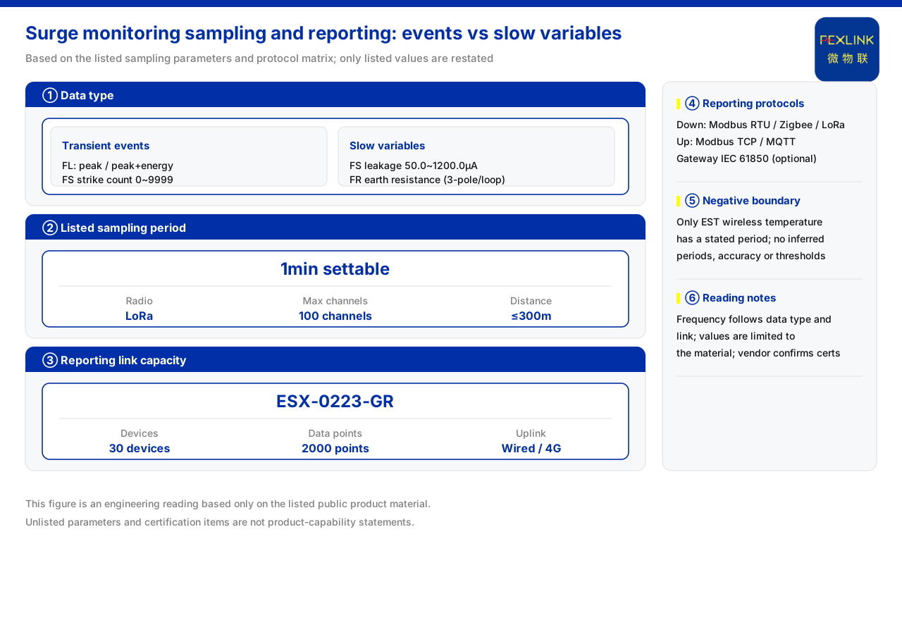
Direct answer
The sampling and reporting frequency of lightning-protection monitoring data cannot be settled by one general value; it first depends on whether the data is a transient event or a slowly varying quantity, and then on how much the link can carry. In the product material, lightning current is a transient event quantity, recorded functionally as a peak value or a peak value plus energy; the lightning-strike count of the surge protective device monitor is an event count, while its leakage current is a continuously acquired slowly varying quantity; the grounding resistance measured by the grounding resistance monitor is also a slowly varying quantity. The only sampling period explicitly given in the material is that of the multi-channel temperature intelligent controller wireless active temperature measurement, which is 1 min and configurable. It follows that the sampling and reporting frequency is determined jointly by the data form and the link capability, rather than by taking one uniform number.
1. First separate event quantities from slowly varying quantities
The first step in determining the sampling and reporting frequency is to classify the data by form. A transient event quantity is short in duration and fast in amplitude change, and what is recorded is whether the event occurred and what its peak or energy was; a slowly varying quantity changes gradually over time and needs continuous, evenly spaced acquisition. The two classes have different requirements: an event quantity is about capture, a slowly varying quantity is about trend. The product material lists lightning current as a transient event quantity and leakage current and grounding resistance as slowly varying quantities, which is exactly how the parameters are organised around this distinction.
2. The sampling meaning for transient event quantities
The product material gives the model rule of the lightning current / transient current monitor, whose detection range is split into two grades, 1 kA to 120 kA and 0.1 kA to 1 kA, while the function field distinguishes peak value from peak value plus energy. This shows that the device records the peak or the peak plus energy of a transient event, not a point-by-point waveform. For such data the sampling strategy serves event capture: the device must recognise a transient that exceeds the trigger threshold and record its peak and energy. The material also lists the waveform-grade models as having no mass-production selection table yet, which indicates that current mass-production models focus on peak-and-energy event recording rather than continuous waveform acquisition.
3. The difference between event counting and slowly varying quantities
The product material records that the surge protective device monitor supports a lightning-strike count of 0 to 9999 times with a minimum trigger of 0.1 kA. This is a typical event count: each strike that reaches the trigger threshold increases the count, giving a cumulative number rather than a continuous curve. The leakage current parameter of the same device is 50.0 to 1200.0 μA with an accuracy of plus or minus 10 μA, a continuously acquired slowly varying quantity. The two appearing on the same class of device shows that sampling and reporting must be handled separately by data form: the counting item updates by event, the leakage item is acquired on a period. The grounding resistance of the grounding resistance monitor is likewise a slowly varying quantity and should be acquired as a slowly changing value.
4. The one sampling period explicitly given in the material
Among all the relevant parameters, the only sampling period explicitly given in the product material is that of the multi-channel temperature intelligent controller wireless active temperature measurement, which uses LoRa communication, supports a maximum of 100 channels, has a sampling period of 1 min configurable, and an effective distance of no more than 300 m. This is a period parameter that can be quoted directly, and it also shows that not every monitoring quantity has its period defined by the material. For a monitoring quantity whose period is not given, one cannot extrapolate from this number and can only determine it in actual commissioning together with the data type and link conditions. Treating 1 min configurable as the known temperature period, rather than as a universal frequency for all lightning-protection monitoring quantities, is the safer reading.
5. Reporting frequency is constrained by link and capacity
Data obtained by sampling must travel upward, and so it is constrained by the link and by capacity. The communication protocol matrix in the product material specifies that devices support Modbus RTU, Zigbee and LoRa on the downlink and Modbus TCP and MQTT on the uplink, with IEC 61850 optional at the gateway level. The intelligent edge-computing gateway has an access capability of 30 devices and 2000 data points, with RS485 downward and wired plus 4G upward. This means the reporting frequency is not decided only at the front end: the device and data-point ceilings of the gateway and the conditions of the uplink network all limit how much data can be uploaded per unit time. Raising the reporting frequency increases the link load, so it must be weighed together with the gateway capacity.
6. The order for determining frequency
Putting the clues together yields an order for determining frequency: first judge whether the data is a transient event or a slowly varying quantity; for event quantities report on event trigger, for slowly varying quantities acquire at even intervals; for quantities whose period is already given in the material adopt the given value directly, for example the 1 min configurable temperature measurement; for quantities without a given period, determine a feasible reporting interval together with the link and gateway capacity; and finally verify during commissioning whether the link is stable. The product material gives no uniform sampling or reporting frequency standard, so the period of one device should not be applied to all monitoring quantities.
7. Setting periods according to the monitoring goal
Combining the data form with the link conditions yields an operable approach. For a transient event such as lightning current, the point is not fixed-interval sampling but ensuring that the trigger threshold and the recording of peak and energy cover the target event; for the lightning-strike count, the point is that no count is lost; for a slowly varying quantity such as leakage current or grounding resistance, the point is evenly spaced acquisition to form a stable trend; and for temperature, the material already gives a 1 min configurable period that can be adopted directly. The reporting stage should then match the sampling: event quantities are reported promptly after the event, slowly varying quantities are reported in batches at longer intervals to lighten the burden on the gateway and the uplink. Because the access capability of the gateway is limited, the period setting must also leave margin so that many devices reporting at once do not cause congestion.
8. Common misconceptions about sampling and reporting
In practice several misconceptions should be avoided. First, treating the period of one device as a universal period for the whole system: the only sampling period explicitly given in the material is the 1 min configurable one for temperature measurement, and other monitoring quantities have no period given, so applying it directly would depart from the data form. Second, focusing only on sampling and ignoring reporting: however high the sampling frequency, if the uplink or the gateway capacity is insufficient the data may still be delayed or lost, while over-reporting a slowly varying quantity also occupies the link. Third, treating a counting item as a slowly varying quantity: the lightning-strike count is an event accumulation that need only be read at fixed intervals, without high-frequency sampling. Fourth, ignoring the effect of the range and trigger threshold on event capture. Only by making these distinctions clear can the sampling and reporting frequency be set to meet the monitoring need without exceeding the link capability.
Scope and limitations
First, this article explains only how to determine the sampling and reporting frequency from the data form and link conditions; the factual boundary is limited to the detection ranges, functions, parameters, protocols and gateway capacities listed in the product material, and no communication standard or engineering code not listed there is introduced.
Second, the product material gives no recommended reporting frequency or latency index for the various monitoring quantities; apart from the 1 min configurable temperature measurement, the statements in this article are general methods induced from the listed data types and do not constitute a communication design.
Third, the ranges, counting range, protocols and access capabilities in this article are all as recorded in the material; this article does not infer the period parameters of unlisted devices from them, nor does it draw inferences about monitoring effect.
Fourth, a specific project must be confirmed in conjunction with the on-site link conditions and the platform carrying capacity; this article provides neither frequency setting values nor a communication configuration list.