 FEXLINK Research Institute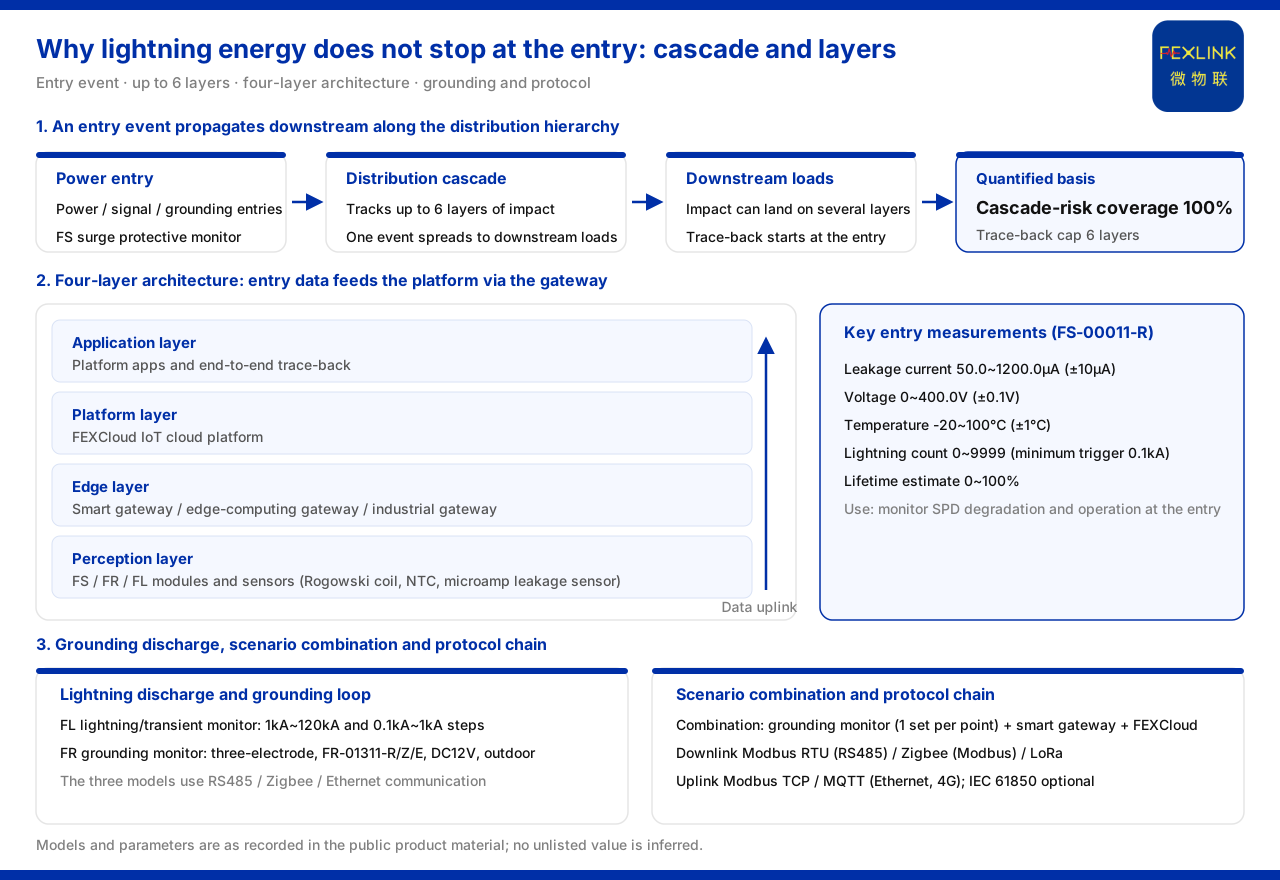
Direct answer
After lightning energy enters through the power-supply entry, it does not stop at the entry device. The product material summarises the monitoring system as a four-layer architecture of perception layer, edge layer, platform layer and application layer, and states that once lightning energy has entered through the power, signal and grounding entries, it is conducted stage by stage along this chain. The same material records that the topology cascade impact calculation of the Wanxiang engine can trace up to 6 layers of topological impact, with a cascade-risk coverage of 100%, meaning that the impact of one entry event can spread downstream along the distribution hierarchy to the loads. The power-supply entry must therefore both monitor the state of the protection devices and leave data for tracing the downstream impact.
1. The power-supply entry is the first link where energy enters
The product material defines the key parameters of the FS surge protective device monitor (e.g. FS-00011-R) as leakage current 50.0~1200.0μA (±10μA), voltage 0~400.0V (±0.1V), temperature -20~100℃ (±1℃), lightning count 0~9999 (minimum trigger 0.1kA) and lifetime estimation 0~100%, with the purpose of monitoring the degradation and operation state of the SPD at the power-supply entry. Placing these quantities on one device shows that the object monitored at the entry is not a single "did it operate", but a combination of the protection device's state in voltage, leakage current, temperature and lifetime. Once the entry device degrades, its subsequent behaviour has to be read out of these quantities. The entry is the first link because it is the boundary through which the external surge arrives; whatever is not handled or recorded there will be passed on to the rest of the distribution system, and the readings at the entry are therefore the earliest description of what the downstream will have to absorb.
2. Energy spreads downstream along the distribution hierarchy
The product material records that the topology cascade impact calculation of the Wanxiang engine can trace up to 6 layers of topological impact, and that among its quantified value indicators the "cascade-risk coverage" is 100%. This wording shows that the material treats one entry event as an impact that can propagate downstream along the distribution hierarchy to the loads, rather than as an isolated event at the entry. "Trace up to 6 layers" gives the scope boundary of the impact analysis: from the entry downward, the effect of the energy can land on loads at several layers. For this reason the significance of entry monitoring is not limited to protecting the entry device; it also provides the starting point for judging the impact on downstream loads.
3. The discharge of lightning current along the grounding path must be reconstructed
Beyond the power path, the product material uses the FL lightning current / transient current monitor (e.g. FL-01222) to record the discharge process of the lightning current. Its detection range has two steps, 1kA~120kA and 0.1kA~1kA, and the function can be peak, peak plus energy, waveform or waveform plus energy; among them FL-01222 (indoor) and FL-01212 (outdoor) support energy (charge / specific energy) monitoring. These functions are used to reconstruct the discharge process of the lightning current along the grounding path. Recording current magnitude and energy separately means that the peak alone is not enough to describe one discharge; the energy dimension adds the dimension of time. A high peak that lasts a very short time and a lower peak that persists both deposit different amounts of energy, so the two readings belong together when the discharge is reconstructed rather than summarised by a single number.
4. Grounding state is the return-path condition of the power path
The lightning current must ultimately be discharged through the ground, so the grounding state directly affects the handling of energy on the power path. The product material records that the FR grounding resistance monitor (e.g. FR-01311-R) uses three-electrode measurement, and that the models FR-01311-R/Z/E are all DC12V and outdoor-installed, corresponding to RS485, Zigbee and Ethernet communication respectively. The material also gives the recommended combination for a typical scenario: in "online grounding-grid monitoring of substations and traction substations", it recommends the grounding resistance monitor (1 set per point) together with the lightning-protection smart gateway and FEXCloud; in "lightning-protection device status monitoring (retrofit of existing SPDs)", it recommends the surge protective device monitor, full-element SPD monitoring or the SPD lightning-protection base. The entry and the grounding are placed in the same combination, which shows that complete coverage of the power path requires both ends to be instrumented.
5. How entry-point data is aggregated and supports trace-back
The four-layer architecture of the product material writes the data chain as perception layer, edge layer, platform layer and application layer. The perception layer contains the various monitoring modules and sensors (Rogowski coil, NTC, microamp-level leakage-current sensor), and the edge layer is borne by the lightning-protection smart gateway, the intelligent edge-computing gateway and the industrial gateway, which perform protocol conversion, edge computing and local caching. The communication protocol matrix further lists that device downlinks support Modbus RTU (RS485), Zigbee (Modbus) and LoRa, while device uplinks support Modbus TCP and MQTT (Ethernet, 4G), with IEC 61850 optionally available at gateway level. Only when the monitoring data of the power-supply entry enters the platform through this protocol chain can it support the trace-back analysis of the impact on downstream loads. The chain matters because the entry readings alone describe one point; it is the aggregation of several points along the same hierarchy that lets the propagation of an event be reconstructed rather than merely observed at the point of entry.
Scope and limitations
First, this article explains only the general wording of how lightning, having entered through the power path, is conducted to the load; the factual boundary is limited to the product material, and no standard clause, parameter, certification or case not listed there is introduced.
Second, the product material gives no quantitative relationship between "entry energy at a site" and "downstream load damage"; the statements about conduction and spread in this article are all drawn from the architecture, the cascade trace-back layer count and the cascade-risk coverage wording already listed in the material.
Third, the models and parameters in this article are all as recorded in the material; this article does not infer the specifications of unlisted models from them, nor does it make performance or effect inferences.
Fourth, the specific monitoring placement must be determined in conjunction with the on-site power-supply entry, grounding conditions and load distribution; this article provides no selection or configuration calculation.