 FEXLINK Research Institute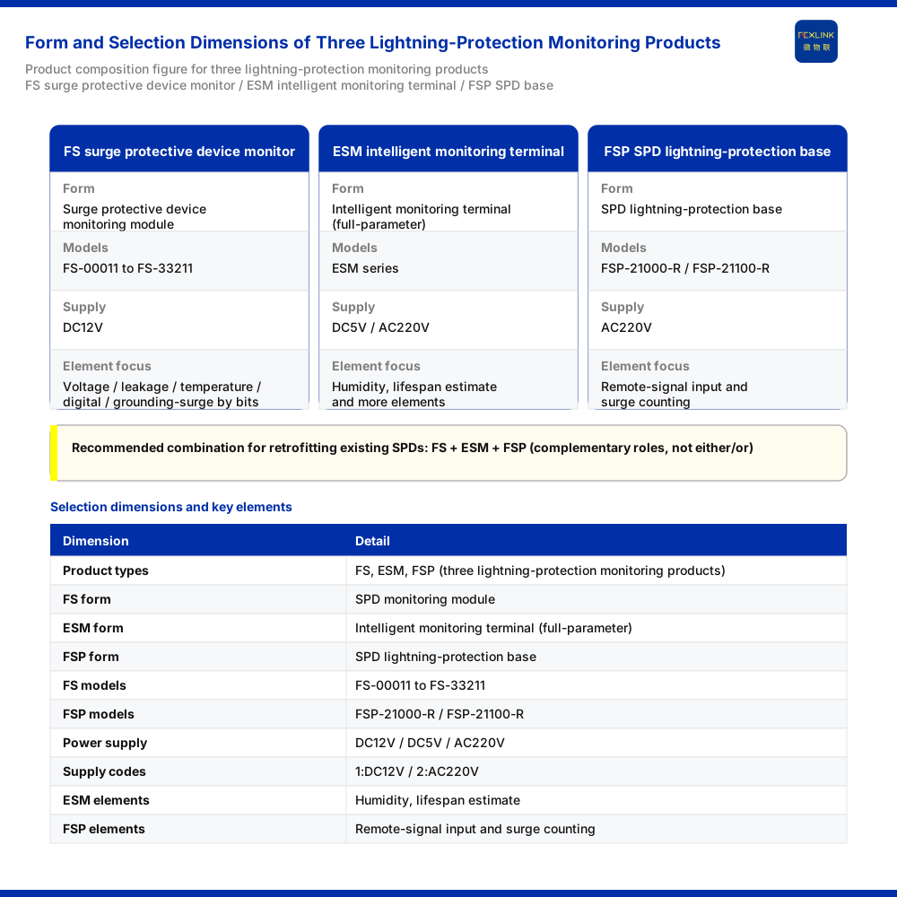
The first question in selection is not "which of the three is better" but three prior questions: which quantities the site must monitor, what power supply the site can provide, and what structure the existing surge protective device (SPD) already has. Around these questions, three monitoring products form a clear division of labour. The FS surge protective device monitor (FS-00011) — a lightning-protection monitoring module — handles status monitoring of the SPD body itself. The ESM intelligent lightning-protection monitoring terminal (ESM-11312-R; SPD monitor) targets terminal-level monitoring with a fuller element set. The FSP SPD lightning-protection base (FSP-21000-R) serves base-type installation with remote-signal input and surge counting. The knowledge base lists all three as one recommended combination in the "lightning-protection device status monitoring (retrofit of existing SPDs)" scenario, which shows they are complementary rather than mutually exclusive alternatives. This article gives a practical method of distinction and selection along three dimensions: element coverage, supply conditions and installation form.
1. What Each of the Three Product Forms Is
The FS surge protective device monitor is positioned as a lightning-protection monitoring module and organises monitoring around the status quantities of the SPD body. Its model rule is FS–[voltage channels][leakage-current channels][temperature channels][digital inputs][grounding/surge]–[communication], its supply is DC12V, and its models range from FS-00011 to FS-33211. In the rule, the bit positions for voltage, leakage current, temperature, digital inputs and grounding/surge are trimmed by "number of channels or presence/absence", while the communication suffix determines the connection method. It therefore suits point-by-point configuration against the monitoring points of an SPD already on site: fit the elements needed, without aiming to cover everything at once.
The ESM intelligent lightning-protection monitoring terminal (SPD monitor) is positioned as a full-element SPD monitoring terminal. Its model rule is ESM–[power][display][phase count][current parameter][version]–[communication], its supply supports both DC5V and AC220V, and its element coverage includes humidity and lifespan estimation. The bit-position combination contains power, display, phase count and current parameter, so it derives several variants from different bit combinations and suits cases that need a fairly complete element set in one pass, presented as a standalone terminal.
The FSP SPD lightning-protection base is positioned as an SPD lightning-protection base. Its models include FSP-21000-R and FSP-21100-R, its supply is AC220V, and it provides remote-signal input and surge counting. It is closer to a "carrying and access" role: it works with an existing lightning-protection device in base form and brings remote signalling and surge counting into the monitoring link, rather than building a fresh set of monitoring points.
2. Dimension One: How Element Coverage Compares
Element coverage is the most direct basis for distinction.
- The FS surge protective device monitor covers voltage, leakage current, temperature, digital inputs and grounding/surge — elements directly related to the SPD body — and can be trimmed by the model rule.
- The ESM intelligent lightning-protection monitoring terminal covers a relatively complete element set including humidity and lifespan estimation, and belongs to the full-element terminal class.
- The FSP SPD lightning-protection base covers two access-type elements: remote-signal input and surge counting.
The judgement follows. If the focus is "SPD body status" (leakage current, temperature, digital inputs, grounding status, surge counting and so on), give priority to the FS surge protective device monitor; if ambient humidity, lifespan estimation and the like should be included as well to form terminal-level full-element monitoring, consider the ESM intelligent lightning-protection monitoring terminal; if an SPD already exists and only remote signalling and surge counting need to enter the monitoring link, consider the FSP SPD lightning-protection base. The three are not a simple ranking by number of elements but face different monitoring objects: the module faces the device body, the terminal faces full elements and the base faces access.
3. Dimension Two: How Supply Conditions Compare
Supply is a hard constraint on selection and must be confirmed against the actual power available on site.
- The FS surge protective device monitor uses a DC12V supply.
- The ESM intelligent lightning-protection monitoring terminal supports two supplies, DC5V and AC220V.
- The FSP SPD lightning-protection base uses an AC220V supply.
The supply-mode codes for lightning-protection products in the knowledge base divide supply into 1: DC12V, 2: AC220V, 3: solar and 4: lithium battery, which can serve as a reference for cross-comparison. Applied to the scenario: where the site can provide only low-voltage DC12V, the FS surge protective device monitor matches the supply condition; where the site can provide DC5V or AC220V, the ESM terminal offers room for choice; where the site supplies the base at AC220V, the FSP base matches. Supply conditions come from the site; a model must never be used in reverse to infer whether the corresponding supply exists, because the supply code is a classification language, not a substitute for a site survey.
4. Dimension Three: How Installation Form and Existing SPD Structure Compare
Installation form determines how a product works with the existing structure.
- The module form (FS surge protective device monitor) suits retrofitting or embedding into existing monitoring points, organised flexibly by point.
- The terminal form (ESM intelligent lightning-protection monitoring terminal) suits standalone installation and centralised presentation of full-element data.
- The base form (FSP SPD lightning-protection base) suits working with a lightning-protection device as a base, taking in remote signalling and surge counting.
A simple rule can be used to judge the existing structure: where an SPD is already installed on site and only status monitoring needs to be added, the module and the base are two common paths; where a new monitoring terminal with a complete element set is wanted, the terminal form is more suitable. This dimension cross-checks with the first two: when the form is right, the elements and supply usually line up; when the three conflict, the site supply and structure are the hard constraints, and the element list should be revisited.
5. A Four-Step Selection Path
Putting the three dimensions together, the choice can be completed in four steps:
- List the elements: first write down the quantities the site must monitor, separating "SPD body status" from "extended elements such as environment and lifespan".
- Check the supply condition: confirm whether the site can provide DC12V, DC5V or AC220V, and treat it as the first threshold of screening.
- Look at the existing structure: confirm whether the site has an existing SPD that needs monitoring added, or needs a new standalone terminal.
- Fix the form and model: converge from the first three steps onto one of the module, terminal or base forms, then determine the specific bit-position combination from the model rule.
In a retrofit scenario for existing SPDs, all three product classes often appear at the same time: the base handles access, while the module or the terminal handles acquisition and presentation, dividing the work rather than replacing one another. Understanding this avoids reading a "combination recommendation" as a "choose one of three".
6. Common Misconceptions
- Treating the three as options at the same level that can replace one another: they face different monitoring objects and installation forms, and a substitution relationship holds only on partly overlapping elements.
- Treating a model rule as a complete model: FS–[voltage channels]... and ESM–[power]... are rules describing bit-position meanings, not complete models that can be ordered directly; a specific model must be determined by the bit-position combination.
- Mixing supply descriptions across variants: within one product family there are variants with different supplies and bit positions, and the supply condition of one variant cannot be applied to the whole family.
- Letting the supply code cover the whole judgement: supply is only one of three dimensions; element coverage and installation structure are equally critical.
7. Applicability and Limits
This article's method of distinction and selection relies only on the supply-mode codes for lightning-protection products in the knowledge base, the model rules and model tables of the FS surge protective device monitor, the ESM intelligent lightning-protection monitoring terminal and the FSP SPD lightning-protection base, and the landing scenario "lightning-protection device status monitoring (retrofit of existing SPDs)". The model examples in the text (such as FS-00011 for the surge protective device monitor, ESM-11312-R for the intelligent lightning-protection monitoring terminal and FSP-21000-R for the SPD lightning-protection base) serve to explain forms and rules; actual configuration should follow the bit-position combination in the corresponding model table and site conditions.
This article does not infer certifications, accuracy, protocol details or engineering cases not listed in the knowledge base, nor does it extend a recommended combination for one scenario into a general conclusion. If the site's element requirements, supply capability or existing SPD structure differ from the assumptions here, return to the element list and the supply check for a fresh judgement rather than applying a model directly. For combination schemes across product families, specific model selection should be carried out after the supply and structure are confirmed.