 FEXLINK Research Institute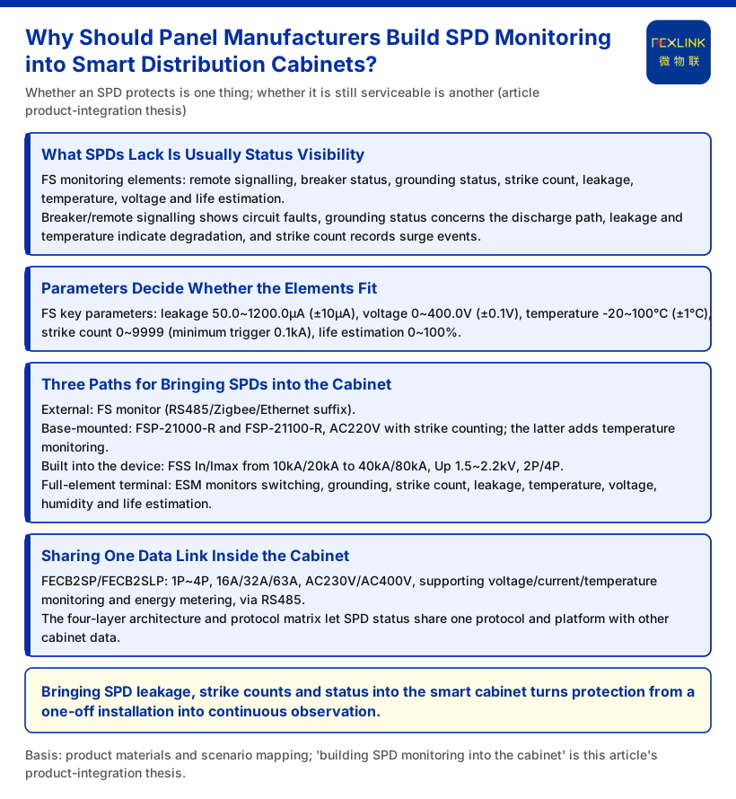
Smart distribution cabinets have spent the past few years promising observability. Voltage, current, temperature, energy and breaker position are all expected to reach the network. Yet one class of device inside the cabinet usually stays outside that picture: the SPD, or surge protective device. An SPD does nothing most of the time, and when it degrades or fails there is often no visible change on the cabinet face. Maintenance crews only start suspecting it after a storm has already damaged downstream equipment. That is why "should a panel manufacturer integrate SPD monitoring into the smart cabinet?" is really a product-integration question. It is not about adding one more meter; it is about whether the cabinet's sensing boundary should include the devices that protect it. Every monitoring element, model and parameter below is limited to entries the knowledge base explicitly lists.
What SPDs Lack Is Usually Status Visibility, Not Protection
Discharge is the SPD's job. The open question is whether the device is still in a usable state, and that condition is normally not collected along with the rest of the cabinet. The knowledge base introduces the FS surge protective device monitor, whose monitoring elements answer exactly that question: remote signalling, air-switch status, grounding status, lightning-strike count, leakage current, temperature, voltage and lifetime estimation. Translated into a cabinet context, each element is concrete. Air-switch status and remote signalling show whether a circuit has been opened or is abnormal; grounding status speaks to whether the discharge path is intact; leakage current and temperature are continuous signs of degradation; lightning-strike count records surge events that have already occurred. Taken together, they turn the SPD from a device you simply install into an object that can be observed continuously.
Parameters Decide Whether Those Elements Can Actually Fit
For the elements to land inside a real cabinet, the range and accuracy of existing products must match the cabinet environment. The knowledge base key parameters for FS are: leakage current 50.0–1200.0 μA (±10 μA), voltage 0–400.0 V (±0.1 V), temperature -20–100 °C (±1 °C), lightning-strike count 0–9999 (minimum trigger 0.1 kA), and lifetime estimation 0–100%. These boundaries show that microamp-level leakage changes, low-voltage-side cabinet voltages, and surge events as small as 0.1 kA all fall within measurable scope. For a panel manufacturer this means SPD monitoring is not a second, high-voltage system bolted on top; it can reuse the low-voltage monitoring and communication links already present in the cabinet.
Three Product Paths for Bringing SPDs into the Cabinet
The knowledge base actually offers three integration positions at different levels, and a manufacturer can choose according to cabinet type and whether the installation is new or existing.
The first is external: use an FS monitor to capture status from SPDs already in service. The knowledge base model table shows FS combining voltage channels, leakage-current channels, temperature channels, switching quantities and grounding/lightning positions, with RS485, Zigbee and Ethernet communication suffixes (for example, the FS-00011-R/Z/E, FS-03211 and FS-33211 series). This path suits cabinets that already have SPDs in place and only need added sensing.
The second is base-mounted: use the FSP SPD lightning-protection base to carry monitoring. The knowledge base lists the FSP-21000-R and FSP-21100-R, both AC220V-powered with digital-tube display, one remote-signalling input and lightning-strike counting; the latter adds temperature monitoring, and both communicate over RS485. Its significance is that monitoring becomes part of the SPD's mounting base rather than a side-attached module.
The third is to build monitoring into the SPD itself: the FSS intelligent surge protective device. The knowledge base describes FSS with In/Imax grading from 10 kA/20 kA up to 40 kA/80 kA, Up of 1.5–2.2 kV, 2P and 4P pole configurations, digital-tube and OLED displays, leakage-current versions with one channel at 2P and three channels at 4P, and the whole series running on AC220V with RS485/Zigbee/Ethernet support. For a newly built smart cabinet, this protection-plus-status device can reduce the device count inside the enclosure.
Where a cabinet needs fuller, all-element monitoring, ESM is another option. The knowledge base positions ESM as an all-element SPD monitoring terminal whose model rule covers power supply (DC5V/AC220V), display (digital tube/OLED), current parameters (0.05–1.2 mA) and form factor; its monitoring elements include switching quantities, grounding status, lightning-strike count, leakage current, temperature, voltage, humidity and lifetime estimation. It fits cabinets that need SPD-related status concentrated in a single terminal.
Making SPDs, Breakers and Gateways Share One Cabinet
Integrating SPD monitoring into a smart cabinet also means answering who shares the data link. The FECB2SP/FECB2SLP smart breakers give the in-cabinet reference: 1P–4P, rated currents of 16 A/32 A/63 A, rated voltages of AC230V/AC400V, all supporting voltage/current/temperature monitoring and energy metering over RS485; the SLP variant adds leakage monitoring and earth-leakage protection. In other words, an RS485 monitoring bus already exists inside the cabinet, so SPD monitoring needs no new physical layer.
Going upward, data is organised by the knowledge base four-layer architecture: the perception layer (FS/FR/FL/ES series monitoring modules, smart meters and sensors), the edge layer (FG/ESX/CW gateways), the platform layer (FEXCloud) and the application layer (visualisation, alarms, reports, inspection); the protocol matrix further specifies device downlink as Modbus RTU (RS485), Zigbee (Modbus) and LoRa, device uplink as Modbus TCP / MQTT (Ethernet, 4G), and IEC 61850 as an optional gateway-level protocol. For a panel manufacturer this answers the post-integration data-consistency question: SPD status quantities can travel over the same protocols and platform as the rest of the cabinet's monitoring data.
At the selection level, the knowledge base scenario mapping also groups related devices. For "lightning-protection device condition monitoring (retrofit of existing SPDs)" the recommended combination is the FS surge protective device monitor / ESM all-element SPD monitoring / FSP lightning-protection base; for "distribution-automation three-phase management" it is the ESB three-phase imbalance monitor plus the FECB2SLP smart breaker. SPD monitoring and in-cabinet electrical monitoring are therefore parallel and combinable within the product system. When specific models and names are used, the terminology locked in the knowledge base should be applied consistently: FS is the surge protective device monitor, ESM the intelligent lightning-protection monitoring terminal (SPD monitor), FSS the intelligent surge protective device, FSP the SPD lightning-protection base, FECB2SP/SLP the smart breaker standard/earth-leakage versions, and SPD the surge protective device.
What This Article Does Not Claim
To keep the integration discussion from being read as a factual conclusion, the article explicitly does not claim the following.
The knowledge base provides no project-level or climate-level data to support them. Third, the article claims no unlisted models, unspecified parameter ranges, certifications, actual effects or customer cases; all device parameters and combinations are limited to those explicitly listed in the knowledge base and must not be extrapolated. Fourth, the article discusses only the integration position and data link of in-cabinet monitoring; it does not address platform usage rates, dedicated arguments about safe system operation, or replacement of existing distribution-cabinet standards or certification requirements.
Conclusion
When a panel manufacturer considers SPD monitoring, it is essentially adding a slice of status visibility: whether an SPD protects is one question, and whether it remains usable is another. The FS, ESM, FSS, FSP and FECB2SP/SLP entries in the knowledge base correspond to external, terminal, body, base and breaker integration positions, and their parameters and protocols are enough to bring them onto the same monitoring link inside the cabinet. Folding SPD leakage current, lightning-strike count and status quantities into the smart cabinet is a step toward turning protection from a one-time installation into something continuously observable. Whether to integrate, and at which layer, should be confirmed item by item against the specific cabinet type and project boundary — and that step still needs project-level review, which this article's integration thesis cannot replace.