 FEXLINK Research Institute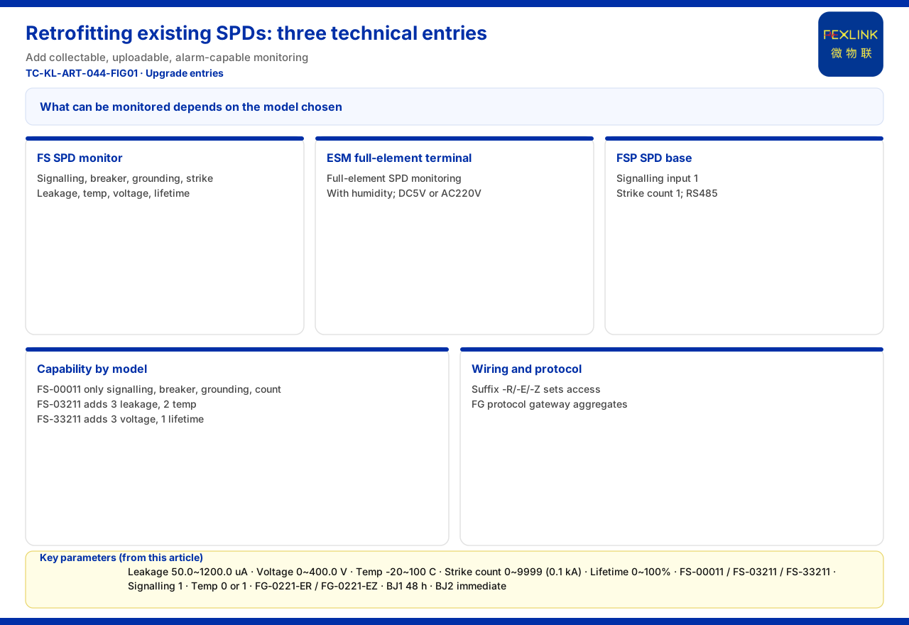
Owning surge protective devices (SPDs) does not make their protection status visible. A smart upgrade usually does not begin by removing the existing SPD but by layering on monitoring that can collect, upload and alarm. FS surge protective device monitors, ESM full-element SPD monitoring, or the FSP lightning-protection base handle status acquisition; RS485, Zigbee, Ethernet or an FG lightning-protection intelligent gateway aggregates it; and the platform turns it into visibility and alarms. The knowledge base lists "lightning-protection device condition monitoring (retrofit of existing SPDs)" as a typical application scenario and gives those three recommended combinations.
1. Why an Existing Device Is "Installed but Invisible"
An existing SPD's core duty is to discharge lightning current or surge, not to report its condition. It performs its protective function but does not naturally produce data a duty engineer can read continuously: whether the air switch has tripped, whether grounding remains reliable, what the strike counter has reached, whether leakage current is drifting. All of this stays at "someone must visit the site to know." Getting that information without replacing the device requires an independent monitoring channel, turning "is it safe?" from a subjective judgement into a continuously readable state.
That is why the knowledge base lists this retrofit scenario separately, and the three optional combinations differ in their monitoring boundaries. In short, the path offered is "add monitoring," not "replace the whole SPD first"; which type, how many, and how they pair with the existing device are site-confirmed selection questions, and no single retrofit process is given.
2. Three Technical Entry Points for the Upgrade
The FS surge protective device monitor covers remote signalling, air-switch status, grounding status, lightning-strike count, leakage current, temperature, voltage and lifetime estimation, with leakage current 50.0~1200.0 μA (±10 μA), voltage 0~400.0 V (±0.1 V), temperature -20~100 ℃ (±1 ℃), strike count 0~9999 (minimum trigger 0.1 kA) and lifetime estimation 0~100%.
The ESM intelligent lightning-protection monitoring terminal (SPD monitor) is a full-element terminal that also covers humidity, with a choice of DC5V or AC220V supply.
The FSP SPD lightning-protection base offers AC220V supply, digital-tube display, one remote-signalling input, one strike-count channel, 0 or 1 temperature channels by model, and RS485 communication — a way to "bring the data out" at an already-installed site.
These three are parallel options; none proves "definitely better." Choose by the elements the site needs, the supply and installation conditions, and whether full-element coverage is required.
3. What Can and Cannot Be Monitored
A smart upgrade easily suggests that once monitoring is installed everything becomes measurable. The knowledge base is more restrained: the boundary is set by the model chosen. In the FS model table, FS-00011 supports only remote signalling, air-switch status, grounding status and strike count; FS-03211 adds three leakage-current and two temperature channels; FS-33211 further adds three voltage and one lifetime-estimation channel. Leakage current, temperature, voltage and lifetime estimation are therefore not default capabilities but options configured by model.
Accordingly, this article does not claim that "any existing SPD plus one monitor will measure every element," nor that parameters such as leakage current and temperature are available without the matching model. It also gives no uniform conclusion on reusing the existing body's remote signalling; whether reusable auxiliary contacts or signalling exist must be confirmed on site and by selection. No compatibility judgement, wiring process or labour hours outside the knowledge base are provided.
4. How Wiring and Protocols Land on Site
To be genuinely used, a monitoring product must land on a communication method. The knowledge base gives the general suffixes: -R is RS485 (Modbus), -E is Ethernet (MQTT), -Z is Zigbee (Modbus), and 4G (MQTT) is reserved on some products. The suffix fixes how one device connects.
Scattered or numerous monitoring points usually need a gateway. The knowledge base defines the FG lightning-protection intelligent gateway as a protocol-conversion type — RS485/Zigbee downlink, Ethernet uplink, DC12V supply, models FG-0221-ER and FG-0221-EZ — converting downlink field-bus data into uplink network data.
At protocol level, gives device downlink as Modbus RTU (RS485), Zigbee (Modbus) and LoRa, and device uplink as Modbus TCP or MQTT (Ethernet, 4G), with IEC 61850 optional at gateway level. The typical link is therefore "monitoring products by suffix — FG or similar gateway — uplink protocol to platform," with no special interface assumed.
5. Where the Data Goes After the Upgrade
Entering the platform is not the end. The knowledge base defines a four-layer architecture of perception, edge, platform and application: the perception layer collects FS/FR/FL/ES series monitoring modules and sensors; the edge layer uses gateways such as FG/ESX/CW for protocol conversion and local caching; the platform layer is FEXCloud; and the application layer presents Web/App visualisation, alarm management, reports and mobile inspection. Existing-SPD data travels this existing path, not a separate system.
On alarm semantics, lists "abnormal open circuit of the grounding resistance" as a non-bypassable red line per GB 50057; a red-line trigger outputs the highest-level alarm directly and takes no part in weighted scoring, and the six-level scheme requires action on BJ1 (20-39 points) within 48 hours and immediate shutdown on BJ2 (0-19 points). This describes a platform-side mechanism, not a disposal commitment for any project.
If scope extends beyond the SPD body, adjacent capability exists: the FR-01311 grounding resistance monitor uses the three-electrode method, DC12V and outdoor installation with RS485/Zigbee/Ethernet, and FL lightning-current/transient-current monitors differ by environment and peak range.
6. Boundaries and Limitations: What This Article Does Not Claim
Second, no model, parameter, certification, compatibility conclusion or case outside the knowledge base is claimed; parameters are limited to the corresponding entries.
Third, no cost saving, payback period, failure-rate reduction or effect commitment is claimed; the quantitative indicators are vendor self-reports, and are not used as a benefit basis.
Fourth, no claim is made that the retrofit can be completed without interrupting operation; the knowledge base gives no live-working or no-shutdown conclusion, so the window and outage arrangements follow site reality.
Fifth, no claim is made that an existing SPD body necessarily has reusable remote signalling or auxiliary contacts; reuse and wiring are site-confirmation matters outside the knowledge base.
Terminology follows the knowledge-base lock: FS = surge protective device monitor, ESM = intelligent lightning-protection monitoring terminal (SPD monitor), FSP = SPD lightning-protection base, FR = grounding resistance monitor, FL = lightning-current/transient-current monitor, FG = lightning-protection intelligent gateway, FEXCloud = IoT cloud platform, SPD = surge protective device.
Conclusion
The point of a smart upgrade for existing SPDs is not to replace the body but to layer on observability: choose an FS, ESM or FSP combination from the scenario, confirm by model which elements can be monitored and how data travels by suffix and FG gateway, then connect to the four-layer architecture and alarm scheme. The real caution is the boundary: what can be monitored is model-decided, while retrofit process, compatibility and benefit effects lie outside the knowledge base's propositions. Writing both "what can be done" and "what this article does not claim" clearly keeps an upgrade plan deliverable and reviewable.