 FEXLINK Research Institute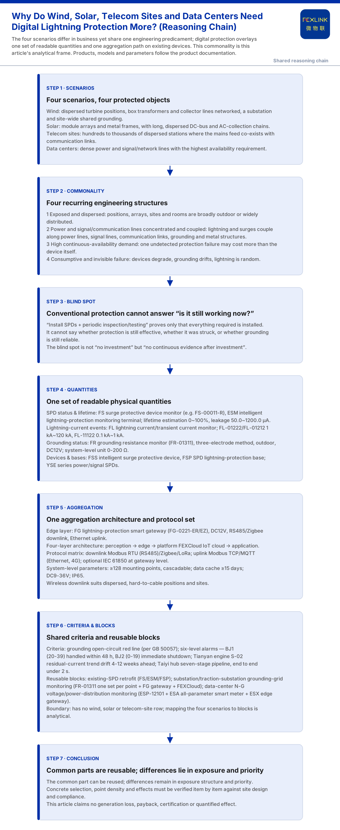
Wind, solar, telecom sites and data centers differ widely, yet share one engineering predicament: exposed and dispersed, power and signal/communication lines concentrated and coupled, high availability demands, and consumptive, invisible protection-device failure. Conventional protection can prove "everything required is installed" but cannot answer "is it still working right now"; digital protection puts the same readable quantities onto one aggregation path.
1. The Commonality Is Engineering Structure, Not Business
The protected objects differ: a wind farm has dispersed turbine positions, networked box transformers and collector lines, plus a substation and site-wide grounding; solar is dominated by module arrays and metal frames with long, dispersed DC-bus and AC-collection chains; telecom sites are hundreds to thousands of dispersed stations where the mains feed co-exists with communication links; a data center has dense power and signal/network lines and the highest availability requirement. Stacked together, four recurring structures appear.
First, exposed and dispersed: positions, arrays, sites and equipment rooms are broadly outdoor-exposed or widely distributed. Second, power and signal/communication lines are concentrated and coupled: long-distance busing, mains feed plus communication links, dense switchgear plus signal wiring mean lightning and surges couple along power lines, signal lines, communication links, grounding and metal structures. Third, continuous availability is demanding, and one undetected protection failure may cost more than the device itself. Fourth, protection-device failure is consumptive and invisible: devices degrade, grounding drifts, lightning is random.
2. The Shared Blind Spot: It Cannot Answer "Is It Still Working Now?"
The basic requirement is "everything required is installed". But "installed" means the design passed, not that "it still works after a strike". An SPD may degrade without visible anomaly; a grounding grid drifts with soil, construction and season; lightning is a low-frequency random event.
The FS surge protective device monitor (FS-00011-R) folds remote signalling, air-switch status, grounding status, strike count, leakage current, temperature, voltage and lifetime estimation into one set because each answers a "does this link still hold" question: leakage 50.0~1200.0 μA (±10 μA), voltage 0~400.0 V (±0.1 V), temperature -20~100 °C (±1 °C), strike count 0~9999 with minimum trigger 0.1 kA, lifetime estimation 0~100%. Grounding status is read continuously by the FR grounding resistance monitor (FR-01311) using the three-electrode method, outdoor-installed, DC12V-powered, supporting RS485/Zigbee/Ethernet. The blind spot is not "no investment" but "no continuous evidence after investment".
3. Commonality One: They Read the Same Physical Quantities
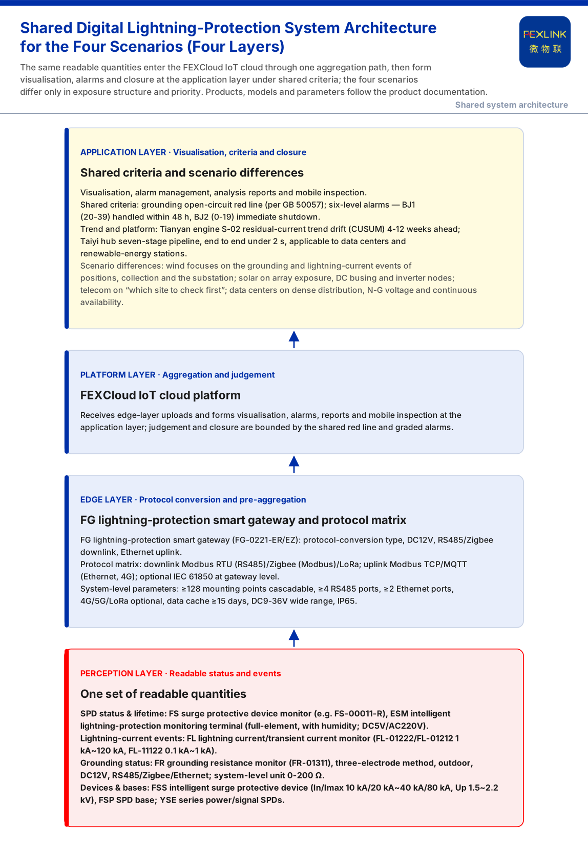
The quantities overlap. First, SPD status and lifetime: besides the FS surge protective device monitor, the ESM intelligent lightning-protection monitoring terminal is "full-element", including humidity, with DC5V or AC220V supply options. Second, lightning-current events: in the FL lightning current/transient current monitor, FL-01222 (indoor) and FL-01212 (outdoor) cover 1 kA~120 kA with energy monitoring, and FL-11122 (indoor) covers 0.1 kA~1 kA. Third, grounding status: the FR grounding resistance monitor and the system-level parameters (monitoring unit 0-200 Ω standard type; gateway mounting ≥128 points, cascadable; data cache ≥15 days; DC9-36V wide-range; IP65). Fourth, devices and bases: the FSS intelligent surge protective device spans In/Imax from 10 kA/20 kA to 40 kA/80 kA, Up 1.5 kV~2.2 kV, AC220V, with leakage versions offering three channels in 4P and one in 2P; the FSP SPD lightning-protection base provides remote-signalling input and strike counting; the YSE series surge protective devices cover the power and signal/network sides.
The scenarios read the same quantities; only point density and installation differ — wind farms layer points, solar sits at busing and inverter nodes, telecom sites at the mains feed and communication links, data centers where power and signal are densest.
4. Commonality Two: Aggregation Rides the Same Architecture and Protocols
The knowledge base gives a four-layer architecture: perception-layer FS/FR/FL/ES modules upload through edge-layer gateways (FG/ESX/CW) to the FEXCloud platform layer, then form visualisation, alarms, reports and mobile inspection at the application layer. Transmission uses the protocol matrix: downlinks include Modbus RTU (RS485), Zigbee (Modbus) and LoRa; uplinks include Modbus TCP / MQTT (Ethernet, 4G); IEC 61850 is optional at gateway level. The FG lightning-protection smart gateway is a protocol-conversion type, with RS485/Zigbee downlink, Ethernet uplink and DC12V supply. Wireless downlink suits dispersed, hard-to-cable sites, and the gateway (≥128 mounting points, cascadable, wide voltage, IP65) suits outdoor deployment. Being shared, the path lets the scenarios overlay one layer of readability on the existing protection system not separate systems.
5. Commonality Three: The Deployment Combinations Are Reusable Blocks
The scenario table offers several blocks: "lightning-arrester condition monitoring (retrofit of existing SPDs)" recommends the FS surge protective device monitor / ESM full-element SPD monitoring / FSP lightning-protection base; "online monitoring of substation and traction-substation grounding grids" recommends FR-01311 (one set per point) + an FG gateway + FEXCloud; "data-center neutral-to-ground voltage / power-distribution monitoring" recommends ESP-12101 + the ESA all-parameter smart meter + the ESX edge gateway; "oil-tank-farm / petrochemical protection" recommends explosion-proof grounding resistance monitoring + FL lightning-current monitoring + FS arrester monitoring.
That table contains no wind, solar or telecom-site row.
6. Criteria Can Be Shared; Differences Remain in Exposure Structure and Priority
The criteria layer is shared too. The knowledge base lists "abnormal open circuit of the grounding resistance" as the non-bypassable red line, per GB 50057; a trigger emits the highest-level alarm and skips weighted computation, and in the six-level scheme BJ1 (20-39) requires action within 48 hours while BJ2 (0-19) requires immediate shutdown. The Tianyan engine S-02 residual-current trend drift (CUSUM) detects a weak mean shift while leakage is still safe, warning 4-12 weeks ahead. The Taiyi intelligent control hub system runs a seven-stage pipeline end to end in under 2 seconds, applicable to data centers and renewable-energy stations; the harmonic fingerprint library includes the FP-12 solar-inverter fingerprint.
Shared criteria do not make the scenarios alike: wind farms focus on the grounding and lightning-current events of positions, collection and the substation; solar on array exposure, DC busing and inverter nodes; telecom sites on "which site to check first"; data centers on dense power distribution, neutral-to-ground voltage and continuous availability.
7. Boundaries: What This Article Does Not Claim
Second, the knowledge base contains no wind, solar or telecom-site row; its data-center combination is ESP-12101 + ESA + ESX, not equivalent to the SPD-condition-monitoring topic. Concrete selection, point density and implementation must be confirmed against site design, grounding conditions and operation requirements.
Third, the quantitative value indicators in the knowledge base (electrical-hazard identification 95%+, alarm compression 80%, 4-12 weeks' warning lead, fault-localisation time from days to 2 hours, MTTR reduced 60%, 8-20% comprehensive energy-saving space) are vendor self-reports; cite them only as vendor capability claims, never as revenue, payback or procurement grounds.
Fourth, this article provides no scenario-specific SPD parameters, point-design rules, generation-loss models or payback calculations, and claims no customer case, certification or performance data.
Conclusion
Wind, solar, telecom sites and data centers need digital lightning protection more not because each lacks a special device, but because they share one engineering predicament: exposed and dispersed, power and signal coupled, high availability demands, consumptive and invisible protection failure. Conventional "install SPDs + periodic inspection/testing" proves only "installed", never "is it still working now". They can use one set of readable quantities and one aggregation path — the FG and the architecture, protocols and system-level parameters — plus the reusable grounding-grid monitoring and existing-SPD retrofit blocks, turning protection effectiveness into continuously visible data. What is common can be reused; concrete schemes and effects still need item-by-item verification.