 FEXLINK Research Institute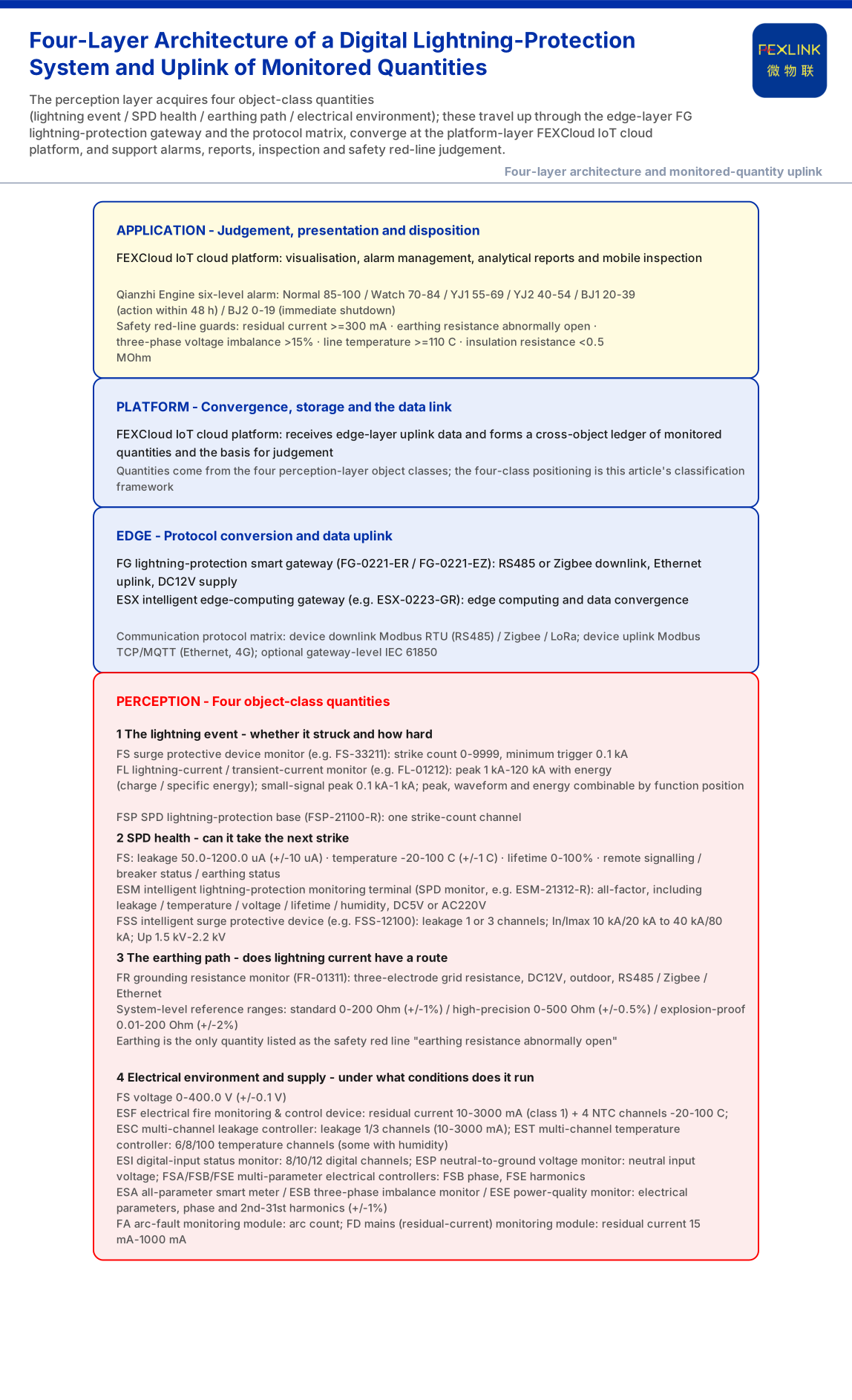
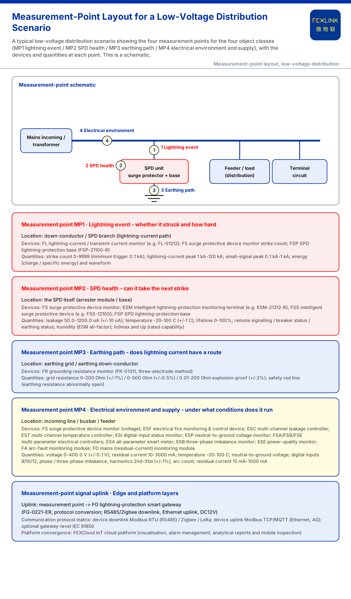
A digital lightning-protection system monitors not one value but a list covering four object classes: the lightning event (whether a strike happened and how large it was), SPD health (whether the arrester can absorb the next strike), the earthing path (whether lightning current has a route to dissipate), and the electrical environment and supply. Only then do design, selection and acceptance testing share a frame of reference.
First, Clarify: The Inventory of Quantities and "Who Sees Them" Are Two Different Things
"What to monitor" is easily confused with "what the customer needs to see". The inventory answers what quantities the system can acquire, over what range and from where — a monitoring-side list. Visibility design answers which quantities go to which role at what granularity — a presentation-side decision (covered separately). This article does only the former, without discussing role tiers, dashboard layout or data-sharing boundaries.
Line One: The Lightning Event Itself — Whether It Struck and How Hard
The first class describes the strike event. The FS surge protective device monitor (FS-33211) records strike counts over 0~9999 times with a minimum trigger of 0.1 kA. To know how strong a strike was, lightning-current parameters are needed: the FL lightning current / transient current monitor (FL-01212) covers peaks of 1 kA~120 kA and supports energy (charge / specific energy) monitoring, while models aimed at small-signal peaks of 0.1 kA~1 kA cover finer transient current; versions combine peak, waveform or waveform-plus-energy. Event quantities are low-frequency and high-consequence: they barely move day to day, but once present they must be traceable. The FSP SPD lightning-protection base (FSP-21100-R) also carries one channel of strike counting.
Line Two: SPD Health — Can It Take the Next Strike?
The second class answers whether the device itself is still sound. The FS monitor provides three continuous observations — leakage current, temperature and lifetime estimate — plus status quantities such as remote signalling, breaker status and earthing status: leakage 50.0~1200.0 uA (±10 uA), temperature -20~100 °C (±1 °C), lifetime estimate 0~100%. Their meanings differ: leakage reflects degradation trend, temperature reflects abnormal heating, and the lifetime estimate turns "when to replace" from experience into a trackable percentage.
Where higher integration is needed, the ESM intelligent lightning-protection monitoring terminal (SPD monitor, e.g. ESM-21312-R) is an all-factor terminal adding humidity to leakage, temperature, voltage and lifetime estimate, with DC5V or AC220V supply; the basic version centres on digital inputs, earthing status, strike count and temperature. With an integrated intelligent arrester, the FSS intelligent surge protective device (e.g. FSS-12100) carries leakage monitoring itself (1 or 3 channels) and states In/Imax (10 kA/20 kA to 40 kA/80 kA) and Up (1.5 kV~2.2 kV). These are "rated capability" quantities and complement "real-time health" quantities.
Line Three: The Earthing Path — Does Lightning Current Have a Route?
The third class is earthing resistance, which decides whether lightning current can be safely dissipated. The FR grounding resistance monitor (FR-01311) measures grid resistance with the three-electrode method, is DC12V-powered and mounted outdoors, and supports RS485, Zigbee or Ethernet. Its reference ranges fall into three grades: standard 0-200 Ω (±1%), high-precision 0-500 Ω (±0.5%) and explosion-proof 0.01-200 Ω (±2%) for tank farms and similar zones. Earthing is the only quantity in the knowledge base listed as red line "earthing resistance abnormally open".
Line Four: Electrical Environment and Supply — Under What Conditions Does It Run?
The fourth class describes the electrical environment around the equipment, where digital lightning protection meets electrical-safety monitoring. Basic parameters come from the FS monitor; the fuller set comes from the second product line:
- Residual current (leakage) and temperature: the ESF electrical fire monitoring & control device (ESF-22110-R) monitors 1 channel of residual current (10~3000 mA, class 1 accuracy) and 4 channels of temperature (NTC -20~100 °C, ±1 °C); the ESC multi-channel leakage controller (ESC-22310-R) monitors 1 or 3 channels of leakage (10~3000 mA); the EST multi-channel temperature controller (EST-12111-R) provides 6, 8 or even 100 channels of wireless LoRa temperature, with some models adding 1 humidity channel.
- Neutral-to-ground voltage and switch status: the ESP neutral-to-ground voltage monitor (ESP-12101-R) monitors neutral input voltage, and the ESI digital-input status monitor (ESI-22110-R) provides 8, 10 or 12 channels of dry-contact input.
- Electrical parameters and power quality: the FSA/FSB/FSE multi-parameter electrical controllers (e.g. SFE-11111-R) share 1 residual-current channel, 3×220/380 V voltage, 4 temperature channels, 2 digital inputs, 2 relay outputs and meter monitoring, with FSB adding phase and FSE adding harmonics; the ESA all-parameter smart meter (ESA-22111-R) provides three-phase parameters, the ESB three-phase imbalance monitor adds phase monitoring, and the ESE power-quality monitor adds 2nd–31st harmonic monitoring (±1%).
- Arc fault and mains residual current: the FA arc-fault module records arc counts, and the FD mains (residual-current) module provides 1 residual-current channel over 15 mA~1000 mA.
Where These Quantities Come From and How They Travel Up
These quantities are not collected in isolation. The knowledge base defines the monitoring system as a four-layer architecture — perception, edge, platform and application: the perception layer acquires data from monitoring modules, smart meters, Rogowski coils, NTCs and microamp leakage sensors, uploads it through edge gateways (including the FG lightning-protection gateway and ESX edge-computing gateway) to the FEXCloud IoT platform, and forms visualisation, alarms, reports and mobile inspection at the application layer. The FG lightning-protection smart gateway (FG-0221-ER) performs protocol conversion, with RS485 or Zigbee downstream, Ethernet upstream and DC12V supply; the transport layer follows the protocol matrix — Modbus RTU (RS485), Zigbee and LoRa downstream, Modbus TCP/MQTT (Ethernet, 4G) upstream, with IEC 61850 optional at gateway level. In other words, "what to monitor" also depends on what the channel can carry.
Why These Quantities: Back to the Purpose
More is not better; the list must serve judgement. The knowledge base anchors the safety floor with five non-bypassable red lines: residual current ≥300 mA (GB 13955), earthing resistance abnormally open (GB 50057), three-phase voltage imbalance >15% (GB/T 15543), line temperature ≥110 °C (GB 16895) and insulation resistance <0.5 MΩ (GB/T 16895); in the same section's six-level alarm scheme, BJ1 (20-39) requires action within 48 hours and BJ2 (0-19) requires immediate shutdown. The residual current, earthing resistance, temperature and three-phase imbalance in the list above are exactly the inputs to these red-line criteria — the direct reason these quantities must be monitored.
Boundaries: What This Article Does Not Claim
Second, this article gives no sampling frequency, reporting period, offline caching and backfill strategy, or point-layout specification; the knowledge base does not provide them.
Third, the quantitative indicators in the knowledge base (electrical-hazard identification 95%+, alarm compression 80%, warning lead 4-12 weeks, fault localisation from days to 2 hours, MTTR reduced 60%, comprehensive energy savings 8-20%) are vendor self-reports. Cite them only as vendor capability claims, never as a promise of coverage sufficiency or project outcome.
Fourth, this article does not duplicate registered articles on customer visibility and role tiers, post-strike data triage, the upgrade path for installed SPDs, engineering-company organisation, long-term O&M contracts or annual-testing-to-continuous-risk services. It answers only what physical quantities the monitoring side should cover.
Conclusion
A digital lightning-protection system needs an inventory covering four object classes: the lightning event (strike count, lightning-current peak and energy), SPD health (leakage, temperature, lifetime estimate and status), the earthing path (earthing resistance) and the electrical environment (voltage, residual current, temperature, neutral-to-ground voltage, switch status, electrical parameters and power quality). Every range and accuracy traces back to a specific knowledge base entry; data travels up through the four-layer architecture and protocol matrix and serves the red lines and tiered alarms. For the owner, the list is a selection and acceptance checklist; for the provider, it is a reminder that a scheme must not stop at "how many sensors were installed" but answer which judgement each quantity supports. The four-class positioning can be borrowed, but point choices must still be confirmed against project conditions and codes.