 FEXLINK Research Institute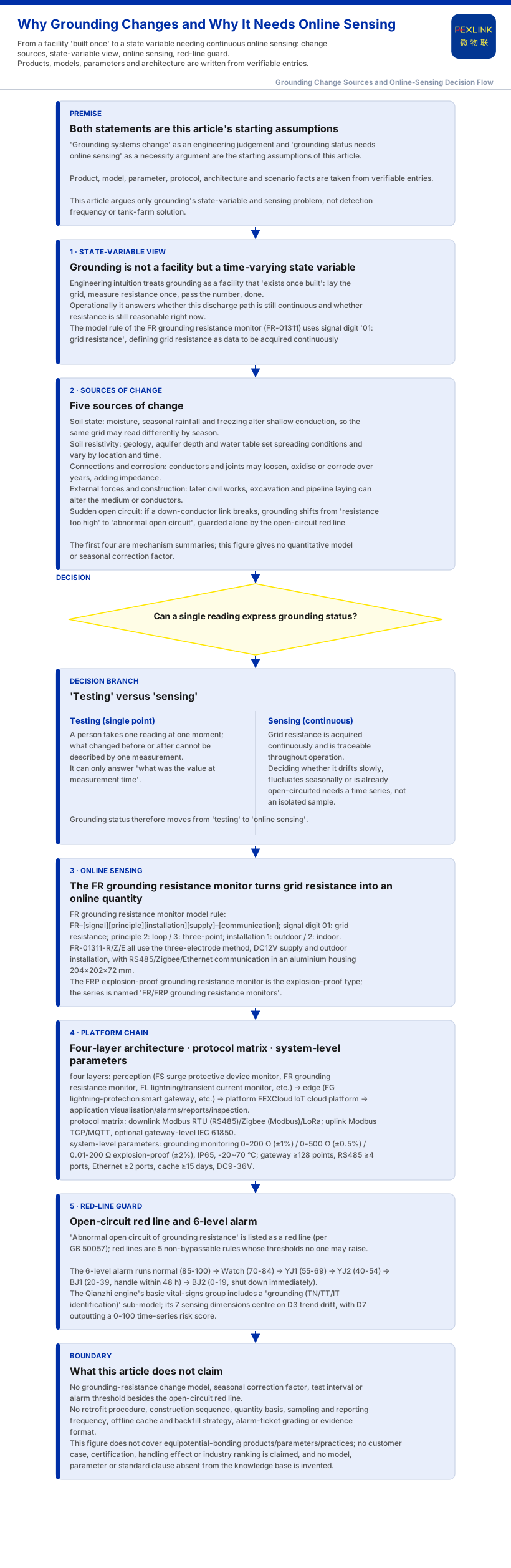
A grounding system is not a static facility built once and left unchanged. It is a state variable that keeps shifting with soil, season, temperature, connections and corrosion; and because it changes, "grounding status" cannot be captured by one-time testing—it needs continuous online sensing. This article answers two basic questions: why grounding changes, and why grounding status needs online sensing. This article covers grounding itself; it does not repeat detection-frequency argument or carry tank-farm engineering solution.
1. Grounding Is a State Variable That Changes
In engineering intuition, grounding is often treated as something that "exists once built": lay the grid, measure the resistance once, pass the number, done. Operationally, grounding answers not "was it built and did it pass" but "is this discharge path still continuous, and is its resistance still reasonable". The knowledge base defines the FR grounding resistance monitor (FR-01311) as the online acquisition device for "grid resistance"; its model rule's signal-acquisition digit is "01: grid resistance", so grid resistance is itself data that must be acquired continuously. The shift is conceptual: grounding's value is not that it was built but that it keeps meeting requirements throughout operation. Once "meeting requirements" is accepted as a time-varying judgement, grounding moves from "facility" to "state variable".
2. Why Grounding Changes: Several Sources of Change
Grounding resistance depends on the impedance the current meets as it spreads from the electrode into the earth, and the medium and connections along that path change. The knowledge base gives no quantitative change model or seasonal correction factor.
First, soil state changes: moisture, seasonal rainfall and freezing alter conduction in surface and shallow layers, so a grid reads differently by season.
Second, soil resistivity varies: geological composition, aquifer depth and water table set the spreading conditions and differ by location and time.
Third, connections and corrosion accumulate: buried conductors and joints can loosen, oxidise or corrode over years, adding impedance to a previously continuous path.
Fourth, external forces and construction can alter the grid: later civil works, excavation and pipeline laying change the medium or conductors around the electrode.
Fifth, a sudden open circuit: if the link between a down-conductor and the grid breaks, grounding shifts from "resistance too high" to "abnormal open circuit"—the case the knowledge base guards with the red line (per GB 50057).
Grounding is thus not a value to measure once and file away, but one acted on by environment, time and external events.
3. Why a Reading Cannot Express Grounding Status
If grounding were a fixed number, one measurement at any moment would do. But it is a state variable: a single measurement gives the reading at "that moment" and cannot describe what changed before or after it. Two concepts differ—"testing" is a person taking one reading at one point in time; "sensing" is having the quantity acquired continuously and traceable throughout operation. Deciding whether grounding is drifting slowly, fluctuating seasonally or already open-circuited needs a time series, not an isolated sample. This article argues only why grounding as a state variable needs continuous sensing, not the efficiency argument that annual testing is insufficient—that is landing point.
4. What Online Sensing Reads: the FR Grounding Resistance Monitor
If grounding status needs continuous sensing, a device must turn grid resistance into an online quantity. The FR grounding resistance monitor in the knowledge base fills this role: its model rule is FR–[signal acquisition][detection principle][installation][supply]–[communication], the detection digit distinguishes 2: loop method / 3: three-point method, the installation digit 1: outdoor / 2: indoor, and the signal digit is 01: grid resistance; FR-01311-R/Z/E all use the three-electrode method, DC12V supply and outdoor installation, with communication matching RS485 / Zigbee / Ethernet, in an aluminium housing 204×202×72 mm. The knowledge base names the series "FR/FRP grounding resistance monitors", where FRP is the explosion-proof type. Note: also records the series applied to online monitoring of railway traction-substation grounding grids and the Jinzhou Port tank farm (10 units per tank), but labels this an internal record, cited only as a source note.
5. From Point to Platform: How Sensing Becomes a System
A point's reading becomes usable status sensing only after it goes up and is aggregated. The knowledge base defines the monitoring system as a four-layer architecture of perception, edge, platform and application: perception acquires via FS/FR/FL/ES series modules, smart meters and sensors; the edge layer (FG/ESX/CW gateways) does protocol conversion, edge computing and local caching; the platform layer, FEXCloud IoT cloud platform, handles device access, time-series databases and AI inference; the application layer outputs visualisation, alarms, reports and inspection. The protocol matrix specifies device downlinks of Modbus RTU (RS485), Zigbee (Modbus) and LoRa, and uplinks of Modbus TCP / MQTT plus optional gateway-level IEC 61850.
System-level reference parameters give engineering headroom: the grounding monitoring unit covers 0-200 Ω (standard, ±1%), 0-500 Ω (high-precision, ±0.5%) and 0.01-200 Ω explosion-proof (Ex d IIB T4/T6 Gb, ±2%), with IP65 protection and -20~70 °C operating temperature (T6 version -40~70 °C); the smart gateway mounts ≥128 points (cascadable), RS485 ≥4 ports, Ethernet ≥2 ports, data cache ≥15 days, DC9-36V wide input. The scenario table gives combinations: "substation / traction-substation grounding-grid online monitoring" recommends FR-01311 (one per point) + FG gateway + FEXCloud; "tank farm / petrochemical lightning and explosion protection" recommends explosion-proof grounding resistance monitoring (Ex d IIB) + FL lightning-current monitoring + FS arrester monitoring.
6. After Sensing: Keeping Change Behind the Red Line
Continuous sensing's value finally shows in whether "change" can be turned into a judgeable signal. The Qianzhi engine runs 50 parameter sub-models (currently 20 core, M01-M20) across 7 sensing dimensions; its basic vital-signs group includes a "grounding (TN/TT/IT identification)" sub-model, and the 7 dimensions centre on D3 trend drift, with D7 outputting a 0-100 time-series risk score. The knowledge base also lists "abnormal open circuit of grounding resistance" as the red line (per GB 50057); red lines are 5 non-bypassable rules whose thresholds no one may raise; the accompanying 6-level alarm runs normal (85-100) → Watch (70-84) → YJ1 (55-69) → YJ2 (40-54) → BJ1 (20-39, handle within 48 h) → BJ2 (0-19, shut down immediately). Online sensing thus connects "will grounding go bad" to trend judgement and red-line guarding.
7. Boundaries: What This Article Does Not Claim
The knowledge base gives no change model, seasonal correction factor, test interval or other alarm threshold besides "abnormal open circuit".
Second, the knowledge base gives only system-level reference parameters; it gives no retrofit procedure, construction sequence, quantity basis, sampling and reporting frequency, offline cache and backfill strategy, alarm-ticket grading rule or evidence format; none are asserted here.
Third, the knowledge base lists no equipotential-bonding products, parameters or practices, so no claim is made about their specification or effect; no customer case, certification, handling effect or industry ranking is claimed, and no model, parameter or standard clause absent from the knowledge base is invented.
Fourth, the FR/FRP application note is an internal record, cited only as a source note. This article covers only grounding's state variable and sensing problem; it does not carry detection-frequency argument, tank-farm solution, or the service model and criteria paradigm landing points.
Conclusion
Grounding systems change because their resistance depends on changing soil and season, soil resistivity, connections and corrosion, external construction and possible sudden open circuits; and precisely because they change, "grounding status" is a state variable, not a fixed reading to file away. Grounding therefore needs not a moment's testing but grid resistance turned into a continuously readable, traceable online quantity. That capability is carried by the FR grounding resistance monitor described in the knowledge base (FR-01311 three-electrode, DC12V, outdoor, RS485/Zigbee/Ethernet; FRP explosion-proof), forming an engineering chain through the four layers, protocol matrix and system-level parameters, and holding the baseline via the red line (GB 50057) and 6-level alarm.