 FEXLINK Research Institute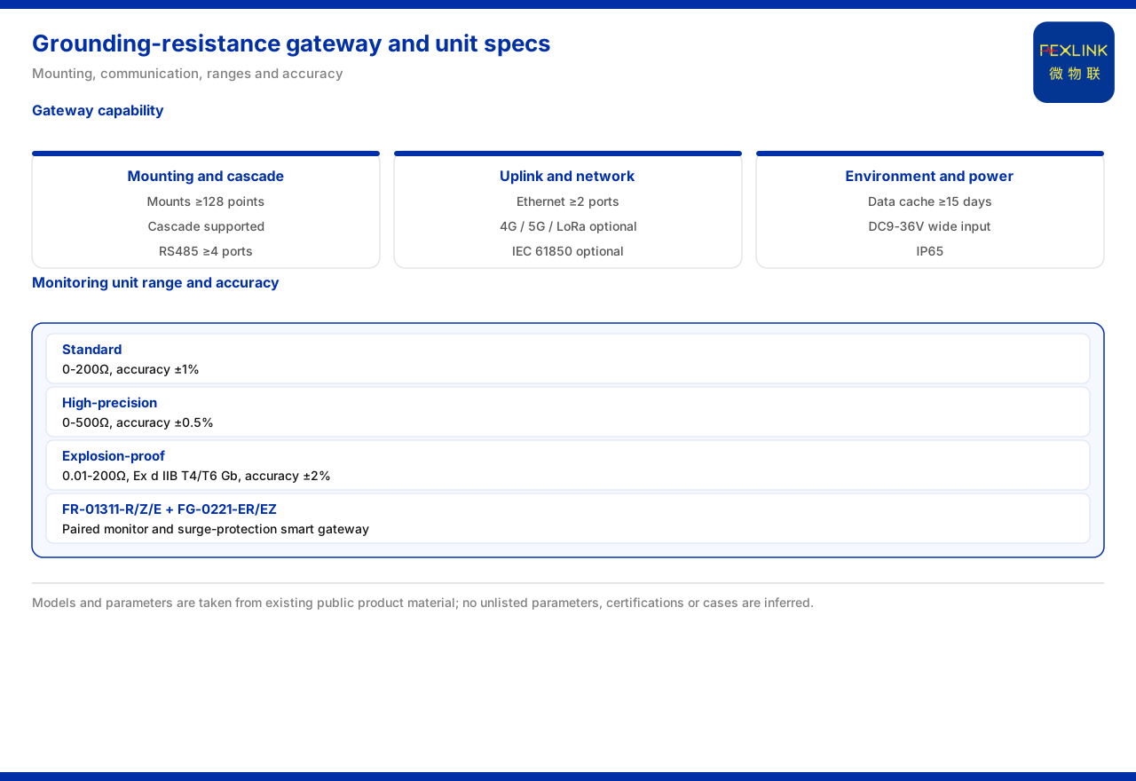
Direct answer
A grounding-resistance online monitoring system is made up of components on the field side and the aggregation side together. The knowledge base gives explicit specifications for the aggregation-side smart gateway: no fewer than 128 mounting points with cascading supported, no fewer than four RS485 channels, no fewer than two Ethernet ports, plus optional 4G, 5G, or LoRa, data caching of no fewer than 15 days, a wide DC9-36V supply, and IP65 protection. The field-side monitoring units are divided into three grades by range and accuracy: a standard type at 0-200Ω (±1%), a high-accuracy type at 0-500Ω (±0.5%), and an explosion-proof type at 0.01-200Ω (±2%).
These specifications answer how many points one system can carry, how long it can store data, in what environment it can operate, and how accurately it measures. Only by reading the gateway's capability together with the monitoring unit's accuracy can one judge whether a grounding-grid online monitoring system matches a site. On this basis the article explains, item by item, the listed specifications of the gateway and the monitoring units, the communication joins, and the typical combination, and marks the parts the knowledge base does not unfold.
System composition and division of labor
A grounding-resistance monitoring system can be split into two segments, field acquisition and edge aggregation. The field side is carried by the grounding resistance monitor (FR-01311-R/Z/E), which the model table records as DC12V, outdoor, three-electrode method, with communication selectable as RS485, Zigbee, or Ethernet; the edge side is carried by the lightning-protection smart gateway (FG-0221-ER / FG-0221-EZ), which the model table records as DC12V, protocol conversion, downlink RS485 and Zigbee, and uplink Ethernet.
The division between the two segments is clear: the monitor measures grounding resistance at the measurement point, and the gateway aggregates data from multiple points and sends it upward. Selection therefore has to answer two questions separately—which monitoring-unit grade is used at each point, and how many points one gateway can cover. These are addressed below.
Gateway mounting capacity and cascading
The knowledge base records the smart gateway of the grounding-resistance monitoring system as mounting no fewer than 128 points and supporting cascading. The mounting point count is the scale of measurement points a single gateway can directly drive; cascading means that when the point count exceeds a single unit's ceiling, more gateways can be added to extend further.
Together these two specifications determine the system's scale ceiling. "No fewer than 128 points" is a lower-bound wording, showing that a single gateway supports at least this scale; cascading leaves the ceiling to the deployment method rather than fixing it on a single device. In selection, estimate the total point count first, then decide the number of gateways accordingly; this reflects reality better than configuring point by point.
Interfaces and uplink options
On interfaces, the knowledge base records the gateway's RS485 as no fewer than four channels and its Ethernet as no fewer than two ports. Multiple RS485 channels corresponds to the multiple acquisition links that can be connected on the downlink, while multiple Ethernet ports corresponds to the wired access capability on the uplink.
On uplink methods, the knowledge base lists 4G, 5G, or LoRa as optional. These methods face different on-site conditions: where wired access is inconvenient, a wireless method can be chosen. It should be noted that these uplink methods and the Ethernet ports described above do not substitute for one another; they provide options for different deployment conditions. This article does not infer the rate or coverage of each method.
Gateway environmental and power-supply adaptation
The knowledge base records the gateway's data caching as no fewer than 15 days, its supply as a wide DC9-36V, and its protection as IP65. The caching capability targets the network-interruption scenario: when the uplink is temporarily unavailable, data can be temporarily stored at the gateway and sent again after recovery. "No fewer than 15 days" shows that this buffer has an explicit duration wording.
The wide DC9-36V supply shows that the gateway tolerates a fairly wide range of supply fluctuation, which facilitates use in sites with differing DC supply conditions. IP65 states its protection rating, aimed at on-site dust and water needs. This article does not infer its operating temperature range or electromagnetic conditions.
Range and accuracy of the monitoring units
Field-side monitoring units are divided into three grades by range and accuracy. The knowledge base records the standard type as 0-200Ω with accuracy ±1%; the high-accuracy type as 0-500Ω with accuracy ±0.5%; and the explosion-proof type as 0.01-200Ω with accuracy ±2%. The difference among the three grades shows up in range and accuracy at the same time, rather than adjusting only one of the two.
In selection, the range determines the upper limit of grounding resistance that can be measured, and accuracy determines how trustworthy the reading is. The standard type covers 0-200Ω and suits most conventional points; the high-accuracy type extends the range to 0-500Ω and tightens accuracy to ±0.5%, suiting cases with higher demands on the reading; the explosion-proof type presses the lower range limit to 0.01Ω, with a range of 0.01-200Ω and accuracy of ±2%, aimed at cases requiring explosion-proof conditions. This article makes no inference about ranges outside a given grade.
Applicable conditions of the explosion-proof monitoring unit
The knowledge base records the explosion-proof monitoring unit as 0.01-200Ω, with an explosion-proof marking of Ex d IIB T4/T6 Gb and accuracy of ±2%. This record shows that the explosion-proof type differs from the standard and high-accuracy types in range and accuracy, and carries an explicit explosion-proof level marking.
Note that the explosion-proof type is aimed at sites with explosion-proof requirements, and its marking and level are hard conditions for selection, not optional decoration. Substituting an ordinary type for the explosion-proof type, or choosing the explosion-proof type where no such requirement exists, both depart from reality. This article does not infer environmental conditions beyond the explosion-proof level, nor does it describe unlisted explosion-proof models.
Communication protocol and upper-layer integration
On communication protocols, the knowledge base's communication-protocol matrix lists IEC 61850 as an optional gateway-level uplink protocol. This shows that, beyond Ethernet ports and wireless methods, the gateway can also use that protocol for the uplink as required by the upper-layer platform.
Read this together with the uplink methods above, and one can understand the gateway as sitting between "multiple on-site interfaces" and "multiple upper-layer protocols": the downlink must receive on-site data such as RS485 and Zigbee, and the uplink must send data out as the platform requires. In selection, whether the protocol matches is often more critical than the number of interfaces, because it determines whether the upper layer can recognize the data. This article does not unfold the concrete implementation of that protocol.
Typical combination and selection order for grounding-grid monitoring
A typical application scenario in the knowledge base lists "online monitoring of the grounding grid of a substation or traction substation" as a combination landing point: a grounding resistance monitor (one set per point) plus a lightning-protection smart gateway, then connected to the IoT cloud platform. This combination corresponds to the specifications above: the monitor is deployed by point, the gateway is selected by point count, and the platform is connected by protocol.
Taken together, selection can advance in four steps. First determine the total point count and which monitoring-unit grade is used at each point; then determine how many gateways are needed according to the point count and distance; then verify whether the gateway's interfaces, caching, supply, and protection satisfy the site; and finally confirm whether the uplink method and protocol agree with the platform. Follow this order, and the specifications are not viewed in isolation but matched item by item around the point scale and site conditions.
Scope and limitations
First, this article restates only what the knowledge base lists, with the factual boundary limited to the smart-gateway specifications of the grounding-resistance monitoring system, the range and accuracy of the monitoring units, the model tables of the grounding resistance monitor and the lightning-protection smart gateway, the communication-protocol matrix, and the grounding-grid online monitoring scenario.
Second, the gateway's mounting point count, cascading, interface counts, optional uplink methods, caching, supply, and protection are cited as listed; this article does not infer its specific topology, rates, or environmental details.
Third, the three grades of range and accuracy of the monitoring units are cited as listed; this article does not infer unlisted range grades.
Fourth, the range, explosion-proof marking, and accuracy of the explosion-proof monitoring unit are cited as listed; this article does not infer environmental conditions beyond its marking level or unlisted models.
Fifth, IEC 61850 as an optional gateway-level uplink protocol is cited as listed in the communication-protocol matrix; this article does not unfold its implementation details.
Sixth, the typical combination and the "one set per point" wording are cited as listed in the typical scenario; this article does not infer implementation details beyond the engineering quantities.