 FEXLINK Research Institute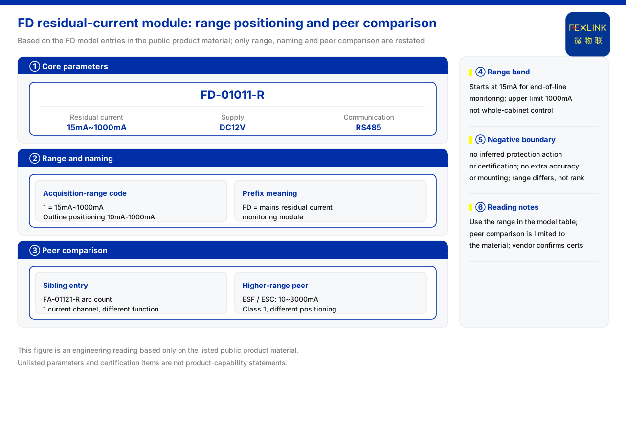
Direct answer
The module's range is 15 mA to 1000 mA, which shows it targets residual-current (commonly called leakage) monitoring at the end of low-voltage distribution rather than electrical fire monitoring of a whole low-voltage cabinet. The materials map the prefix to a mains residual-current monitoring module, and the current-acquisition range code 1 recorded in the same section is exactly 15 mA~1000 mA, while the product outline positions it as 10 mA-1000 mA. By contrast, the electrical fire monitoring and control device and the multi-channel leakage-current monitoring and control device have a residual-current range of 10~3000 mA with accuracy class 1, a clearly higher upper limit. The range difference is therefore not just a matter of numbers but a direct expression of different product positioning and applicable objects.
1. Which interval the range falls in
The listed model is a 1-channel residual-current device with a range of 15 mA to 1000 mA, a DC12V supply, and RS485 communication. The model rule also notes that current-acquisition range code 1 corresponds to 15 mA~1000 mA, while the product outline positions this module class as 10 mA-1000 mA. The materials also mention that the model supports expansion bits for voltage and temperature channels. Read together, it is a module whose main observed object is a relatively small residual current, with a lower limit close to the milliamp level and an upper limit of 1000 mA. For an end circuit or single-point monitoring, this interval is enough to cover common leakage changes.
2. Prefix meaning and product positioning
The product model quick reference maps the prefix to a mains residual-current monitoring module. This naming gives its place: it monitors residual current in a mains circuit and belongs to the sensing layer's acquisition modules. Compared with a controller that can stand as a complete set, a module is closer to a field acquisition unit and depends on a back-end gateway and platform to organize the data. The 15 mA to 1000 mA first says that it is designed to capture smaller residual-current changes rather than cover a wide residual-current range. Its relationship with gateway and platform also means it takes an acquisition rather than a control role in the overall monitoring scheme.
3. Range difference from the electrical fire controller
The materials record that the electrical fire monitoring and control device has a residual current of 10~3000 mA with accuracy class 1, a higher upper limit than this module. The controller's model rule gives current-parameter settings of 10~3000 mA and 5 A/0.5 mA. This shows the controller faces a wider range, with an upper limit reaching 3000 mA that exactly covers the interval above this module's limit. If the site must cover a larger residual current, this module's single range may be insufficient, and a controller-class model is more suitable. The height of the upper limit directly corresponds to the size of the monitored object.
4. Range difference from the multi-channel leakage controller
The materials likewise record that the multi-channel leakage-current monitoring and control device has a leakage range of 10~3000 mA with accuracy class 1, also higher than this module. Its value lies in extending residual-current monitoring to 1 or 3 channels. In range terms it sits in the same class as the electrical fire controller, while in channel terms it offers multi-channel capability. This module sits in the smaller range class, positioned for single-point, end residual-current monitoring. The difference among the three can be summarized as range class and channel count, corresponding respectively to the user's needs for monitoring scope and monitoring points.
5. The same section also has an arc monitoring module
The materials list, in the same section, a fault arc-fault monitoring module whose monitored object is the arc count, fitted with 1 current channel, a DC12V supply, and RS485 communication. It and this module respectively serve arc monitoring and residual-current monitoring: one records how often arc events occur, the other records the value of the residual current. Listing them adjacently shows that at the same level, objects can be divided by monitoring type. Selection should first confirm whether arcs or residual current are to be monitored, then choose within the corresponding module, avoiding any mixing of the two monitored quantities.
6. Selection meaning read from the range
Taken together, the 15 mA to 1000 mA range means three things: first, it is a sensing-layer mains residual-current monitoring module with a lower limit close to the milliamp level; second, its upper limit is below the 10~3000 mA class of the electrical fire controller and the multi-channel leakage controller, so its coverage is narrower; third, it is distinguished from the arc monitoring module in the same section by monitored object. If the target is a small-range residual current at an end circuit, this module fits; if the target is a larger residual current or a complete control set, a wider-range model should be considered. The materials give no conversion across ranges, so no inference should be made.
7. Matching the range with installation conditions
Beyond the range itself, supply and communication also indicate the installation form of this module class. The materials record a DC12V supply and RS485 communication, showing it is designed for local acquisition and bus networking, commonly near an end distribution box or monitoring point. The smaller range and the low-voltage DC supply work together toward placement close to the monitored circuit rather than a centralized complete host. By contrast, a controller using AC supply with display and relay output looks more like a model that can stand as a complete set. If localized, distributed acquisition of end residual current is needed, the module form is more suitable; if centralized display and control are needed, a complete model should be chosen. Reading range, supply, and installation form together gives a full picture of the product role corresponding to 15 mA to 1000 mA.
8. Correctly understanding the range boundary
The upper and lower limits of a range represent the measurable scope, not a protection setting or an alarm threshold. The materials give the module's measurement capability, not its operating condition; they do not give the alarm threshold or operating time corresponding to this range. The 15 mA to 1000 mA should therefore be used to explain how large a residual current the module can measure, not turned into a setting value. If the target residual current is near the upper limit, whether measurement margin remains should be confirmed; if near the lower limit, whether resolution is sufficient should be confirmed. These judgments should rest on the listed range without introducing unlisted thresholds or accuracy inference. Treating the range as a capability boundary rather than an operating condition is the premise for understanding this parameter.
Scope and limitations
First, this article explains only the positioning and differences reflected by the module's range, and the factual boundary is limited to the range, supply, communication, and same-section models listed in the materials; it introduces no unlisted standard clause, protection threshold, or engineering code.
Second, the materials give no quantitative correspondence between this range and the protected circuit current or conductor cross-section; the comparison in the text is a general statement induced from the listed ranges and does not constitute protection-setting design.
Third, the range, supply, and communication parameters are those already recorded in the materials; this article does not infer the specifications of unlisted models from them, nor does it infer alarm effects.
Fourth, a specific selection must be confirmed against the actual residual-current range and packaged requirements of the end circuit; this article provides no range calculation or configuration list.