 FEXLINK Research Institute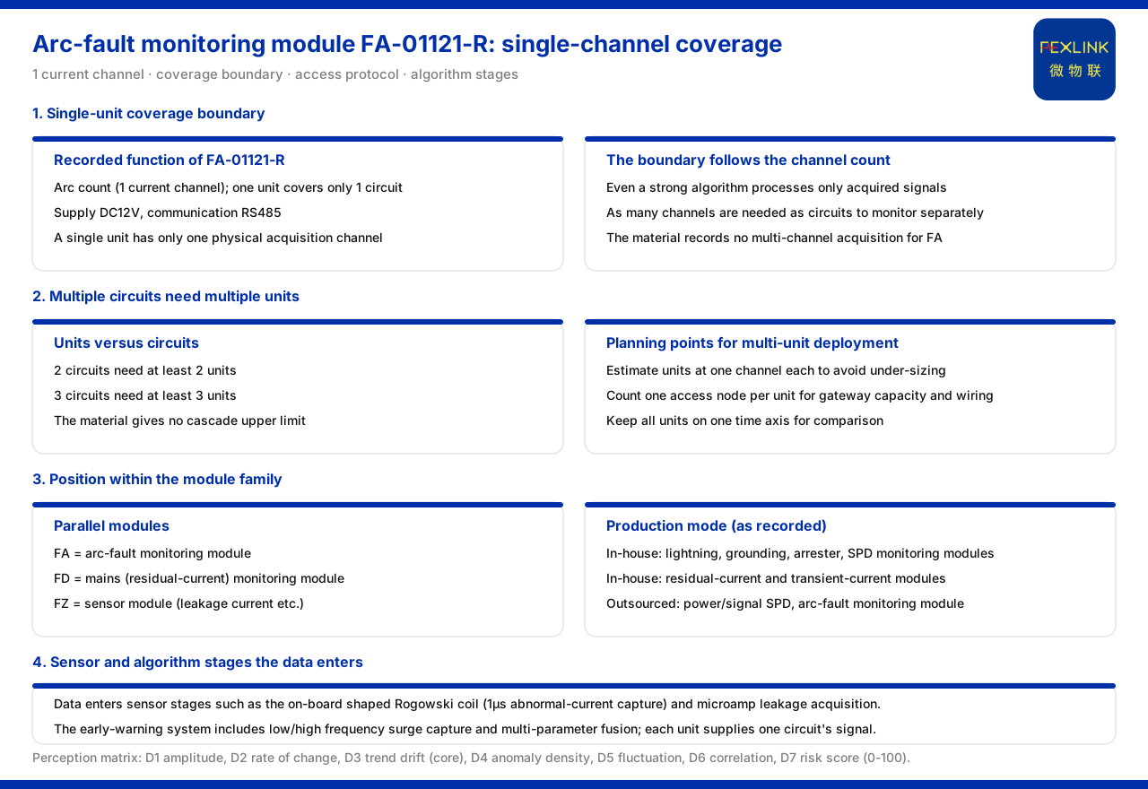
Direct answer
The arc-fault monitoring module (FA-01121-R) is recorded with the function of arc count and 1-channel current, meaning a single device covers only one current circuit. From this it can be judged that if a distribution system has several current circuits requiring arc monitoring, multiple devices are usually needed according to the circuit count. The knowledge base records that the FA is powered by DC12V and communicates over RS485, which falls in the device downlink protocol category; the knowledge base does not give an upper limit on the number of arc-fault monitoring modules that can be cascaded. The conclusion in this article that "multiple circuits need multiple units" is derived from the capability boundary of 1 channel per unit and is an application-layer extrapolation.
What 1 channel means
The knowledge base model table records that the function of FA-01121-R is arc count, with a monitoring object of 1-channel current. This means the current channel acquired by a single device is only 1 channel, and its coverage boundary is 1 current circuit. Understanding this boundary matters: it determines the range of arc events one device can observe and the number of units needed in multi-circuit scenarios. Reading "1 channel" as a coverage unit is more accurate than treating it as a general function description, because it directly corresponds to the number of monitorable circuits.
Multiple circuits need multiple units
From the boundary of 1 channel per unit it can be directly derived: 2 circuits need at least 2 units, 3 circuits need at least 3 units, and so on. The knowledge base does not give an upper limit on cascadable FA units, nor a statement that "one unit can be extended to multiple channels"; therefore, configuring units by covering 1 channel each and by circuit count is the deployment convention confirmable within the current material boundary. Whether and how cascading is possible should follow the latest product material and project plan. Note that what is derived here is the correspondence between unit count and circuit count, not a specific conclusion on how many units a given site should deploy.
Why the coverage boundary is determined by channel count
The coverage of arc monitoring depends on the acquisition channel count, not on algorithm or platform capability. The knowledge base records the monitoring object of FA-01121-R as 1-channel current, showing that the physical acquisition channel of the device is only 1 channel; however strong the algorithm link, it can only process signals already acquired. The coverage boundary should therefore be understood from the acquisition side: as many circuits as need independent monitoring require as many acquisition channels. Mapping the coverage boundary to acquisition channels avoids a common misjudgment — assuming that more circuits are automatically covered once connected to the platform. The knowledge base does not record that the FA has multi-channel acquisition capability, so understanding its coverage boundary as 1 channel is the prudent statement within the material boundary.
The place of arc monitoring in the module system
The knowledge base places the FA arc-fault monitoring module and the FD mains residual-current monitoring module side by side in the same section; the product model quick-reference records FA as arc-fault monitoring module, FD as mains residual-current monitoring module, and FZ as sensor module (leakage current, etc.). It can be seen that arc monitoring is one link in the modular product system, side by side with other monitoring modules. The knowledge base also records the production mode: in-house production includes lightning current, grounding resistance, surge arrester and lightning-protection device monitoring modules and residual-current and transient-current monitoring modules; outsourcing includes power and signal surge protective devices, arc-fault monitoring modules, intelligent air switches and power-quality monitoring modules. Accordingly, the arc-fault monitoring module is listed as an outsourced production item in the material.
Which sensors and algorithm links the data enters
The knowledge base lists the on-board special-shaped Rogowski coil (1μs-level abnormal-current capture) and microamp-level leakage-current acquisition as two core sensor technologies, where 1μs is the time scale of abnormal-current capture. On the algorithm side, the core technologies of the electrical hazard early-warning system (charging-safety scenario) include low-frequency wavelet and high-frequency surge capture (microsecond-level abnormal-current capture), multi-parameter fusion intelligent algorithm, charging-hazard heat map, and dynamic data monitoring plus multi-dimensional intelligent analysis. The Qianzhi engine (discrimination) defines a 7-dimensional perception matrix: D1 amplitude, D2 rate of change, D3 trend drift (core), D4 anomaly density, D5 fluctuation amplitude, D6 association verification, D7 time-series risk score (0 to 100 comprehensive decision). Arc-event data ultimately enter these sensors and algorithm links. For a single device, its 1-channel current signal enters the above links and can be analyzed along dimensions such as amplitude, rate of change and trend; but it always provides the signal of only one circuit, and cross-circuit association analysis needs the data of multiple units together.
How the data is connected
The communication protocol matrix of the knowledge base records that the device downlink protocols are Modbus RTU (RS485), Zigbee (Modbus) and LoRa. The RS485 communication of FA-01121-R falls in this downlink protocol category and can be connected to a gateway and then uplinked to the platform. During deployment, each device is connected to one circuit by 1-channel current and then aggregated over RS485. Since each unit covers only 1 channel, the number of access points on the aggregation side increases with the circuit count, and this should be counted in gateway capacity and cabling arrangements during planning.
Planning points for multi-unit deployment
When circuits are many and multiple units are needed, planning should at least address three points: first, estimate units by "1 channel per unit" to avoid under-provisioning by an idealized multi-channel assumption; second, count the access side as one node per unit, considering gateway capacity and cabling together; third, ensure on the data side that the data of all units are comparable on the same time axis, otherwise the multi-unit data are merely independent records. The knowledge base does not give a cascade upper limit, so the expansion method between multiple units should not be presupposed; planning should assume independent access per unit and be adjusted once explicit material is available. The above points are an application-layer extrapolation, and the specific plan is determined by the engineering party.
Order of deployment judgment
Drawing the above together, judgment can follow the order of "count circuits, set unit count, connect protocols, aggregate data": first count clearly the current circuits requiring arc monitoring; then determine the unit count by 1 channel per unit; confirm that communication is connected over downlink protocols such as RS485; and finally aggregate to the platform through a gateway. Since the knowledge base does not give a cascade upper limit or coverage-expansion rule, the correspondence between unit count and circuits should be estimated at 1 channel per unit, and the specific configuration is determined by the engineering party together with the field circuit structure. The above order is an application-layer extrapolation.
Scope and limitations
- The functions, channel counts, protocols, production mode and algorithm statements in this article are limited to the existing records of the knowledge base, and do not infer product certifications (such as AFCI or AFDD certification).
- The knowledge base does not give an upper limit on the number of cascadable arc-fault monitoring modules, nor a statement that "one unit extends to multiple channels"; "multiple circuits need multiple units" in the text is an application-layer extrapolation.
- The production mode, sensor and algorithm items in the text are existing records of the knowledge base and do not constitute a commitment to results of a specific product.
- Actual measuring points and unit counts must be determined by the electrical-safety engineering party together with the field circuit structure; this article does not provide calculation conclusions for configuration quantity.