 微物联研究院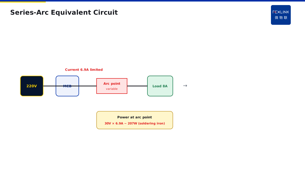
Direct Answer
The ammeter reads normal, the breaker stays quiet, yet the junction box is charred. This happens on site every year. The cause is not a failed protection device—it is that a series arc is itself a voltage-drop, current-limiting physical process. The fault point becomes a variable resistor wired in series, clamping total current below the rated value so the thermal-magnetic release never reaches its trip threshold.
But the arc point itself runs at 3000–6000 °C, hot enough to carbonise insulation and ignite wood shavings and plastics nearby. Low current does not mean safe; normal current does not mean no fault. This is the mechanism behind "overcurrent and RCD protection both nominal, yet an electrical fire still happened."
The fix is not a bigger breaker or a more sensitive RCD—it is an FA arc-fault monitor that reads the arc's waveform signature.
1. The Math: How an Arc Clamps the Current
Take a 10 A socket circuit normally feeding an 8 A kettle. A terminal loosens mid-run and starts arcing.
An arc is not a wire—it is a column of ionised air. Breakdown turns the air into a plasma with a voltage drop and a resistance. Measured values for low-voltage, small-current arcs show a 20–40 V drop, with resistance varying sharply with arc length and temperature.
Plug it into the loop equation:
Supply 220 V = U_load + V_arc Current I = (220 - V_arc) / R_load
Normal: V_arc = 0, I = 8 A, U_load = 220 V.
Arcing: V_arc = 30 V, U_load drops to 190 V, current becomes I = 190 / 27.5 ≈ 6.9 A.
See it? Current dropped from 8 A to 6.9 A. Not only did it not exceed the rating—it went *down*.
The MCB's thermal release is set at 1.13×In (11.3 A). Current is below rating, so it does nothing. The RCD measures the vector sum of L and N; series-arc current leaves on L and returns on N, vector sum is zero, the RCD stays dead.
But the arc point? 30 V drop × 6.9 A ≈ 207 W of power dumped into a pinhead-sized discharge. Concentrated into 1 mm², that is an electric soldering iron—hot enough to carbonise insulation in seconds.
2. Why Field Inspection Misses It
Traditional inspection tools are essentially blind to series arcs:
- Ammeter: sees 6.9 A, normal.
- IR thermography: if the insulation jacket is intact, the hotspot is hidden underneath; by the time IR picks it up, the jacket is burning and smoking.
- Hand on the enclosure: temperature normal.
- Electrician's ear: the faint hiss of a small-current arc is lost in factory noise.
One office socket circuit in a park had a clean inspection record: current 7.2 A, insulation resistance 200 MΩ, leakage 0.8 mA. Three months later it caught fire overnight. Post-incident forensics found a loose copper sleeve in the socket, arcing through the jacket to ignite a sofa. No traditional protection operated at any point.
3. Why Traditional Protection Is Collectively Silent
| Protection | Measures | Response to series arc |
|---|---|---|
| MCB thermal-magnetic | RMS current + time | Current limited, falls; no trip |
| Electronic trip unit | RMS current + dI/dt | Same, no dI/dt spike |
| RCD | L/N vector difference | Series arc has L = N; zero difference |
| Residual-current fire monitor | Earth leakage | Series arc does not leak to earth |
This is exactly why GB/T 31143 (IEC 62606) was written and why a new device class called the AFDD was invented. It does not make existing protection more sensitive—that just causes nuisance trips. It switches the physical quantity measured: not *how much* current, but *what shape* the waveform has.
4. The Arc's Fingerprint on the Waveform
A normal sinusoidal current is smooth, continuous and symmetric at zero-crossing. A series arc leaves three signatures:
High-frequency bursts. The arc is intermittent gas discharge; each re-ignition emits a high-frequency spike at 10–100 kHz. Normal loads (motors, lamps, computer PSUs) do not.
Current zero-dead-time. At the current zero-crossing, the voltage is too low to maintain ionisation, so the arc briefly extinguishes for tens to hundreds of microseconds before reigniting. The waveform shows a flat "zero-current gap" around the zero-crossing.
Waveform distortion and amplitude jitter. Arc resistance is unstable; each half-cycle differs in amplitude and shape—some high, some clipped, some spiked. Over time the envelope jitters.
The FA-01121-R module samples circuit current in real time and runs signature-recognition algorithms: high-frequency threshold, zero-dead-time detection, and continuous half-cycle distortion rate. GB/T 31143 defines standard test circuits A1, A2, B1; FA must operate correctly under those tests and not nuisance-trip under normal loads.
5. From Post-Fire Extinguishing to Pre-Fire Alarm
Traditional protection trips at thresholds: 11.3 A thermal, 30 mA RCD, 0.5 MΩ insulation. These are all "already broken" markers.
Arc monitoring alarms when the *waveform* looks wrong:
- High-frequency component appears → possible loose arcing, warning;
- Stable zero-dead-time gaps → active arcing, alarm;
- N consecutive half-cycles over distortion threshold → trip or interlock.
One data-centre rack supply circuit: FA detected a slow rise in high-frequency content. Qianzhi engine ran trend analysis and judged terminal heating developing. O&R inspected the live aviation plug with a borescope, found one pin oxidised, and replaced it in the maintenance window—no outage.
6. Why Not Just Make the MCB More Sensitive?
On site people ask: if series arcs are dangerous, why not set the MCB from 1.13 to 1.05?
You cannot. MCB thermal trips are inverse-time; the lower the setting, the more normal inrush causes nuisance trips. Motor start-up, PSU surge, compressor start-up are 5–10× rated current. If you squeeze the threshold to 1.05, these normal conditions trip the breaker, and O&R will bypass the protection—more dangerous.
The problem is not sensitivity; it is the wrong physical quantity. You cannot weigh something with a ruler by adjusting the scale. The arc waveform is the right scale.
7. The Complete Protection Chain After Adding FA
An end circuit needs three layers:
MCB (overcurrent/short) → RCD (earth leakage) → FA/AFDD (series arc)
Each layer measures a different physical quantity; none replaces another. GB/T 31143 recommends AFDD on end circuits in homes, commercial buildings, schools, hospitals, elderly homes and museums—places where an electrical fire has the worst consequences.
The FEXLINK FA-01121-R is not a breaker itself; it is an online monitoring module wired in series, sampling current waveform and uploading arc signatures to Qianzhi engine, where Taiyi dispatches work orders. It works alongside MCB and RCD without changing the existing distribution layout.
Scope and Limitations
Applies to series-arc fire mechanism analysis and protection selection in 0.4 kV LV systems. HV DC, hazardous-area and PV DC-side arcs require dedicated standards. Power-density figures are typical; actual values vary with arc length, current and electrode material. FA-01121-R is a FEXLINK capability reference; selection follows the latest catalogue.