 微物联研究院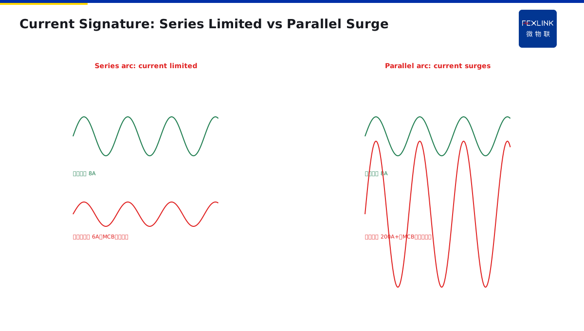
Direct Answer
An electric arc fault is not one phenomenon—it is three physically different events, differing in where they sit in the circuit, how much current they draw, and whether overcurrent protection can see them:
- Series arc: occurs at a broken conductor, loose terminal, or worn contact. It acts like a variable resistor inserted in series; the current does not rise, it is *limited* to—or below—the load rating. Overcurrent protection is blind to it. This is the most dangerous and most hidden type.
- Parallel arc: occurs between adjacent line conductors or line-to-neutral. It is a low-resistance path across the supply, current is large, and it behaves like a short circuit. Overcurrent protection trips quickly.
- Earth arc: occurs between a line conductor and earth (PE, damp wall, metal pipe). Current depends on the earthing arrangement—near a short circuit in TN systems, only a few to tens of amperes in TT.
The most troublesome, most common arc in real electrical fires is the series arc—because it fools the MCB, the RCD, and the ammeter.
1. Where Each Arc Sits in the Circuit
Picture a typical single-phase circuit: supply → MCB → conductor → load → return.
Series arcs appear where the conductor itself is discontinuous:
- A cable half-chewed by rodents, remaining strands arcing;
- A terminal-block screw loose, arcing between copper and lug;
- An oxidised plug or worn socket contact, contact resistance fluctuating;
- An extension lead stepped on for years, internal strands broken.
All these are on the "current must flow through" path—the arc is in series.
Parallel arcs appear between two conductors that should not touch:
- L and N insulation both worn through, copper touching copper;
- L-to-L2 breakdown in a three-phase system;
- Water in a cable trench bridging two conductors.
This is across the supply, equivalent to an extra load.
Earth arcs appear between a line conductor and earth:
- L insulation damaged against a metal trunking;
- L passing through a damp wall, arcing to the masonry;
- Internal L-to-frame contact, frame bonded to PE.
2. Current Signature: Why the Series Arc Is Sneakiest
| Type | Equivalent circuit | Loop current | Overcurrent protection | RCD |
|---|---|---|---|---|
| Series arc | A variable R_arc in series | Limited, below load rating | No trip | No trip |
| Parallel arc | A low-resistance path in parallel | Surges toward short circuit | Fast trip | No trip |
| Earth arc | Earth-leakage resistance | Large in TN / small in TT | TN trips / TT may not | TT trips |
Why series-arc current cannot rise
Consider a 10 A socket circuit normally feeding an 8 A kettle. The wire loosens mid-run and arcs. An arc is a gas-discharge channel with a 20–40 V drop, and its resistance varies wildly with length and temperature.
Loop equation: 220 V = I × R_load + V_arc
The arc eats 30 V, the load sees 190 V, and current may drop from 8 A to 6 A. The MCB's thermal-magnetic release needs 1.13×In (11.3 A) or more. Current has gone *down*—the breaker stays silent.
But the arc point itself? The arc is a 3000–6000 °C plasma, hot enough to carbonise surrounding insulation and ignite combustible decoration. This is the physical mechanism behind "ammeter normal, breaker silent, then fire."
Why parallel arcs are easier to defend
A parallel arc is effectively a short circuit across the supply terminals. Fault current may be hundreds of amperes; the MCB trips in milliseconds, and the RCD sees the earth leakage. The hard part is catching it *before* the breakdown—when insulation is already half damaged but not yet touching.
Earth arcs depend on earthing arrangement
In TN-S, the frame is directly earthed; L-to-frame is a hard short, overcurrent protection trips instantly. In TT, frame earth resistance may be 30 Ω; L-to-frame current is 220/30 ≈ 7.3 A—overcurrent protection does not act, but this exceeds 30 mA so the RCD trips. That is why TT systems require RCDs by code.
3. Field Signatures of Each Type
Series arc on site
- A socket sparking intermittently, fixed by pressing the plug;
- A burning smell at a terminal, yet voltage and current read normal;
- An extension cord hot at the plug, but the plug has no over-temperature warning;
- An IR scan shows only a pinhead hotspot.
Parallel arc on site
- Cable trench smoking, two conductors blackened where they touch;
- Carbonised tracking between phase busbars in a switchboard;
- Breaker trips, reset works, trips again a few days later.
Earth arc on site
- Tingling on a damp basement enclosure;
- Rust marks and burn spots on a steel-conduit run;
- RCD trips repeatedly but no obvious leakage point.
4. Why Traditional Protection Is Collectively Silent on Series Arcs
Walk through each traditional protection against a series arc:
- MCB overcurrent: measures loop RMS current. Series-arc current is limited, it falls, the MCB does nothing.
- RCD: measures the vector sum of L and N. Series-arc current leaves on L and returns on N, vector sum is zero—the RCD cannot see it.
- Thermal/electronic trip: also looks at RMS current and time. Same result.
- IR thermography: by the time you see a hotspot, the arc has been burning for a while. Early arcs hide under the insulation.
This is exactly why GB/T 31143 (equivalent to IEC 62606) exists, and why a new device class called the AFDD was invented: it does not look at *how much* current—it looks at the *shape* of the current waveform.
5. FA Arc-Fault Module Closes the Series-Arc Blind Spot
The FEXLINK FA-01121-R arc-fault monitoring module is wired in series in the circuit. It measures not how large the current is, but what the waveform looks like:
- High-frequency content: arcing produces 10 kHz–100 kHz bursts absent in normal loads;
- Current zero-dead-time: at each current zero-crossing, the arc briefly extinguishes and re-ignites, leaving a visible gap;
- Waveform distortion: the sine wave is clipped into an irregular shape with steepened edges and spikes.
FA analyses these signatures continuously. When it recognises a sustained arc waveform (per GB/T 31143 test circuits A1/A2/B1 etc.), it alarms or trips. It is not a replacement for MCB or RCD—it is the third blind spot:
- MCB handles overload/short circuit;
- RCD handles earth leakage;
- FA/AFDD handles arcing.
6. One Table to Remember the Three Arcs
| Series arc | Parallel arc | Earth arc | |
|---|---|---|---|
| Location | Broken wire / loose joint | L-N or L-L | L-PE / earth |
| Current | Limited, reduced | Surges near short | Large TN / small TT |
| MCB | No trip | Trips | TN trips / TT not |
| RCD | No trip | No trip | TT trips |
| FA/AFDD | Trip (core target) | Trips | Trips |
| Typical scene | Loose terminal, oxidised plug | Insulation breakdown touching | L touching frame |
| Risk level | Highest (hidden) | Medium (cut fast) | Depends on earthing |
Scope and Limitations
Applies to arc-fault physics and protection selection in 0.4 kV LV systems. HV, DC and hazardous-area systems require dedicated standards. FA-01121-R is a FEXLINK capability reference; selection follows the latest catalogue. Scenes are generic, not project-specific.