 FEXLINK Research Institute
The short answer
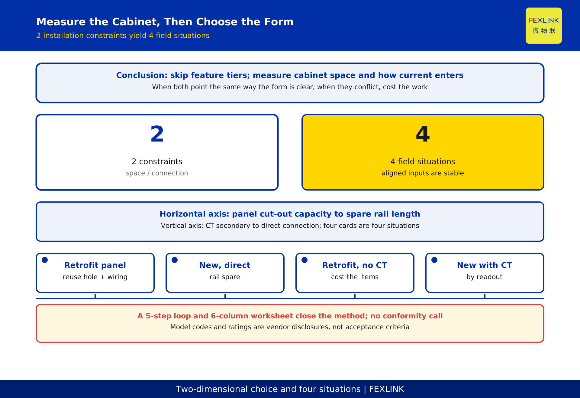
Do not ask which meter is better. Ask two cabinet constraints: how much mounting space is left, and whether this circuit's current arrives through a current transformer or goes straight into the meter terminals. On those axes, embedded ZSA versus DIN-rail ESA stops being a capability ranking and becomes two installation paths with different landing points.
Compressed to one line: a door that already has a cut-out, a circuit that already has CTs, and a door that cannot be remade all point to the embedded form; spare rail, a direct-fed larger current, and the wish to add or move devices later point to the rail form. What decides it is whether the cut-out can change, the rail is long enough, secondary wiring must be pulled, and the main circuit can be taken out of service.
The rest gives a 2×2 table, a 6-column worksheet, and a 5-step loop for recomputing the conclusion at your cabinet.
Reframe the choice as 2 installation constraints
Selection drifts toward a feature checklist: phase data, harmonics, pulse output, communications ports. Those answer "what to measure", not "will it fit and can it be wired". Either form may meet the same requirement; choose the wrong form and the right features cannot be installed.
Rewrite the question as 2 constraints you can measure on site:
- Space constraint: can the door be cut, is the opening taken, how much rail remains, will body depth foul the duct. A tape measure and the cabinet drawing answer this.
- Connection constraint: does current arrive as a low-current secondary signal from a current transformer (CT), or is main-circuit current brought straight to the meter terminals. The former adds secondary wiring and polarity; the latter adds conductor cross-section, terminal joints, and routing.
Both are physical facts, checkable at handover. That makes the judgement reusable.
Criterion one: panel space decides where you can mount
An embedded meter begins with a panel cut-out: the body inserts from outside the door, held by bezel and clips, display facing outward. Cut-out dimensions are tied to the body outline, and a machined opening is irreversible. On a retrofit door, old meter openings, pushbuttons, lamps, and nameplates leave only the space they did not take. If the new outline does not match, either cut a new position (reassess door strength and ingress protection) or fit an adapter frame (extra depth, sealing, flatness).
A rail meter never touches the panel. The body clips onto a standard rail inside the cabinet; position follows rail length and usable depth, there is no door display window, and readings are taken inside or carried over communications. The cost moves inside: continuous rail, body width and depth, conductor bend radius, and clearance to devices, ducts, and terminal blocks.
So the first cut is not "which form uses less space" but "on which surface is the spare capacity". Generous panel space plus front-facing readout favours embedded; a full door with free rail favours rail. Measure both before concluding.
Criterion two: how current reaches the meter matters more than the range
Ratings are not the watershed; the last stretch of the circuit is.
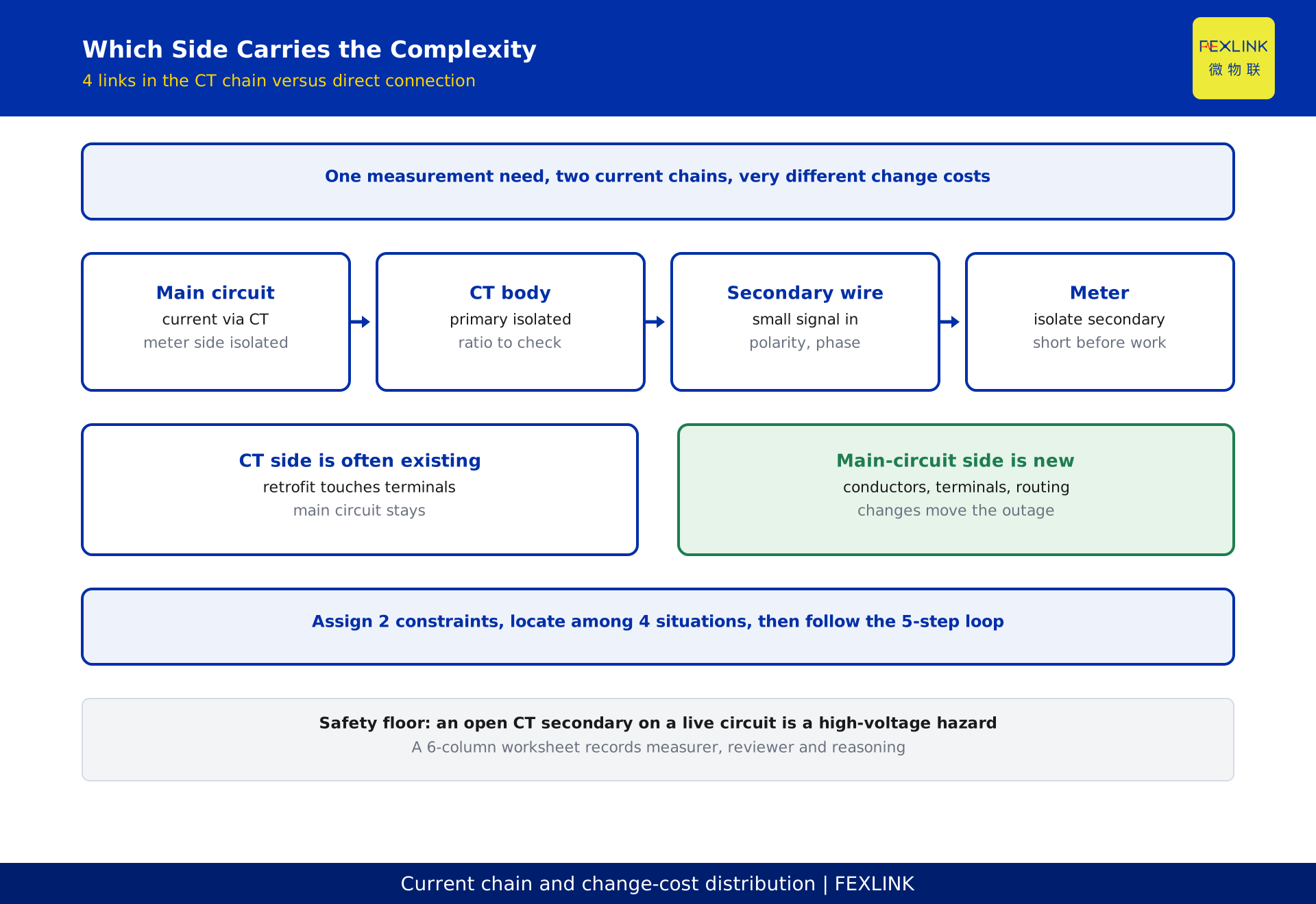
Through a CT: main-circuit current becomes a low-current secondary signal carried to the meter over secondary wiring. The meter side carries no main-circuit current, conductors are thin, and the metering circuit can be isolated on the secondary side. The price is a longer chain: CT bodies, mounting, secondary wiring, terminals, and checks of ratio, polarity, and phase sequence. In a three-phase circuit a reversed polarity or wrong phase order corrupts power direction and energy accumulation, and may not show at energisation. There is also a safety floor: an open CT secondary on a live circuit can produce dangerous high voltage, so short or isolate it before removing a meter.
Direct connection: main-circuit current enters the meter terminals directly. The chain is short, with no CT, no secondary wiring, and no ratio or polarity check. The price lands on the main circuit: conductor cross-section matched to current, sound terminals tightened as specified, busbar or cable routing that respects bend radius and heat dissipation, and an outage with verification and isolation for maintenance. One secondary loop removed, one main-circuit work package added.
So the second criterion is where complexity sits, not whether the range suffices. A retrofit with CTs barely touches the main circuit; a new direct-fed build is cleaner the other way.
A 2×2 map of 4 field situations
Cross cut-out capacity with connection method and you get 4 typical situations. These are tendencies, not verdicts.
| Situation | Space | Connection | Smoother form | Main reason |
|---|---|---|---|---|
| Retrofit panel | Old cut-out, rail tight | CT and secondary exist | Embedded ZSA | Reuse hole and secondary circuit |
| New cabinet, direct | Rail spare, door not cut | Direct connection | DIN-rail ESA | Shortest chain, easy to add |
| Retrofit, no CT | Hole in door, rail tight | New chain needed | Cost the items | Compare CT against main-circuit rework |
| New cabinet with CT | Rail spare, door can be cut | CT exists | Cost the items | Either fits; decide by readout and upkeep |
The first two rows are the main conclusion. In the last two, cost the items and write the reasoning down.
Why a panel cut-out is irreversible and a rail position is not
A door hole is one-time machining; a rail position is adjustable assembly.
An irreversible cut-out front-loads the embedded decision. Once cut to one outline, any later change of form means reworking the door. An adapter frame only exchanges "recut" for "add a transition layer"; the decision stays irreversible. Retrofit cabinets lean embedded not because it is better but because the hole is already there and following it is cheapest.
Rail mounting is assembly: add rail, shift a clip, add or remove a meter, without damaging the cabinet. Expansion is friendly, because a later circuit looks for free rail. Correction is friendly, because a bad position costs little to adjust. Spare rail is still not infinite; usable depth and heat bind.
The same asymmetry sits in the current chain. CT secondary rework happens at terminals and wiring, usually without touching the main circuit; a change to direct connection lands on the main circuit and brings an outage. "Embedded plus CT" and "rail plus direct" are two distributions of change cost, not just two outlines.
Hidden work: CT, secondary wiring, and main-circuit labour
The chain is invisible; list what each side adds.
CT side: transformer bodies and mounting, secondary wiring and identification, terminal blocks and shorting links, ratio, polarity and phase-sequence checks, secondary isolation during maintenance. Many items, but all on the low-voltage signal side, usually with no main-circuit outage.
Main-circuit side: conductor cross-section, terminal specification and tightening, busbar or cable routing and bend radius, heat dissipation and phase clearance, outage, verification, isolation, and a post-restoration check. Each item relates to main-circuit current and any change moves the outage plan.
Shared items: labelling, circuit correspondence, drawing and register updates, final verification.
So the right question is not "which side has fewer items" but "which items already exist". On a retrofit circuit with CTs and secondary wiring, the CT side is mostly existing, and direct connection would build a new main-circuit chain. In a new cabinet the main circuit is installed anyway, so direct connection removes the whole secondary loop. That is why one meter reaches opposite conclusions on different sites.
A redacted example: two circuits at one site
A constructed, redacted example; labels and values are illustrative.
Circuit A, retrofit. The door has an old meter opening and indicator lamps; rail inside is occupied by terminal blocks and duct. The circuit already had current transformers with secondary wiring to a terminal block. Measurement reads "hole in door, no free rail, CT and secondary wiring present". Both constraints point to reusing the existing surface and secondary circuit, so embedded ZSA is preferred: keep the hole, reterminate secondary wiring, leave the main circuit untouched, keep the outage short. Choosing rail would require finding internal space and rebuilding the chain, at greater cost.
Circuit B, new cabinet. The door should not be cut again; continuous rail and usable depth were reserved inside. Current is brought in directly by design, with no CT. Measurement reads "door cannot be cut, rail spare, direct connection". Both constraints point to DIN-rail ESA: clipping the body on completes installation, the chain is shortest, and later circuits still find free rail.
Similar requirements, opposite conclusions: measure the cabinet first.
Four common mis-selections
First, compare rating numbers without the connection chain. A rating answers "can it measure", not "how is it mounted". Datasheet-only selection easily produces a retrofit design that rebuilds the main circuit.
Second, treat spare rail as unlimited. Adding later is not adding without limit. Body width and depth, bend radius, and clearance to duct and terminal blocks must be measured on the drawing; with insufficient depth a meter that fits may still be impossible to cool or service.
Third, ignore that a cut-out is irreversible. A panel hole is one-time machining; changing form means reworking the door or adding an adapter frame. Treat it as editable and a later swap concentrates cost on the door.
Fourth, service a CT secondary without isolation. An open secondary on a live circuit presents dangerous high voltage. Short it or isolate before removing a meter, then recheck polarity and phase sequence. This is a safety floor, not a step to skip.
The first two misuse space; the last two are construction and safety constraints.
A 6-column worksheet and a 5-step loop
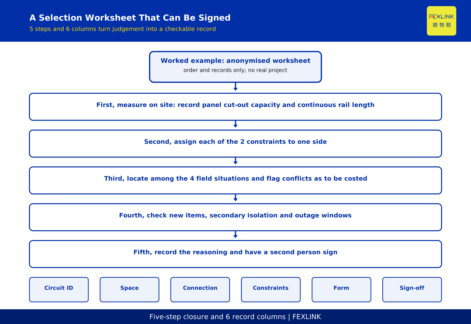
Leave a record so the next person can check the judgement. Give each circuit one row of a 6-column worksheet:
| Column | What to record |
|---|---|
| Circuit ID | Circuit label and cabinet number |
| Space allowance | Cut-out positions, continuous rail length, usable depth |
| Connection | CT secondary or direct; existing or new |
| Construction | Outage possible, secondary isolation, terminal conditions |
| Form tendency | Embedded ZSA, DIN-rail ESA, or to be costed |
| Review record | Measurer, reviewer, date, short reasoning |
The matching 5-step loop: measure on site and record both allowances; assign each constraint to one side; locate the quadrant and flag conflicts as to be costed; check the hidden-work list for new items and outage windows; record reasoning and have a second person sign.
The value is turning "I think" into "it was measured".
Frequently asked questions (FAQ)
Q: Can both forms be mixed in one cabinet?
Yes, common on retrofit work. Judge each circuit on its own conditions. Label the form in the register so spares are not ordered for the wrong shape.
Q: If the door was cut for an embedded meter, can I switch to rail?
Yes, but two bills come due: blanking or reusing the hole, and moving the current chain from CT secondary to the main circuit. Usually not worth it, unless rail is unusually good and the main circuit was due for rework.
Q: A circuit already has CTs. Does that force the embedded form?
No. A CT only points the connection constraint toward the secondary side; space is still measured on its own. With continuous rail and a door that should not be cut, a rail meter fed from a CT secondary is equally valid.
Q: Can a rail meter accept a CT signal?
Mounting form and connection method are independent; there is no binding. Whether it can depends on the signal chain and terminal design, to be settled from design documents and site wiring. No model-specific claims are made here.
Q: What if the two constraints point in opposite directions?
Do not decide by preference. List new items and outage windows on both sides, compare which already exist, and record the reasoning. If still close, prefer the side with lower irreversibility.
Scope and limitations
This article compares only mounting form and the current connection chain. It does not cover feature tiers, accuracy classes, protocols, tariffs, or data platforms. No standard number, clause number, or conformity judgement is cited. Remarks on CT secondary work and outages are general cautions; actual work must follow safety rules, design documents, and manufacturer material.
Model codes and current ratings in registration material are vendor-disclosed data. This article does not treat them as first-hand facts, nor as a selection conclusion, acceptance criterion, or technical commitment. The example is constructed and redacted, with no real project or measured values, and cannot predict any specific installation.
Every conclusion is subject to site measurement and the cabinet drawing: whether a cut-out can be made, free rail exists, CTs and secondary wiring are present, and the main circuit can be scheduled for an outage. Until those four are measured, any tendency is preliminary. This draft needs review by a qualified electrical engineer.
Frequently Asked Questions
Embedded ZSA vs DIN-Rail ESA
Do not ask which meter is better