 FEXLINK Research Institute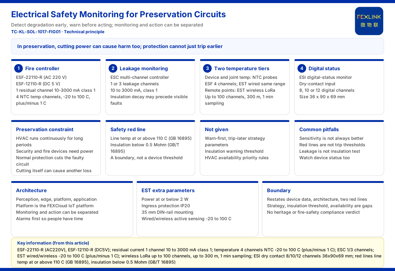
Direct Answer
The difficulty of micro-environment electrical safety in museums and archives is that two goals restrain each other: constant temperature and humidity and security equipment need continuous power, yet once an electrical fault occurs it may cause a fire, or the protective action may cut power and unbalance the micro-environment, which in turn damages the collection. The usable means given by the product documentation are mainly continuous monitoring: the ESF electrical fire monitoring and control device provides residual-current and temperature monitoring, the ESC multi-channel leakage-current monitoring and control device provides more leakage measuring points, the EST multi-channel temperature intelligent controller provides wired and wireless temperature monitoring, and the ESI digital-input status monitor provides switching-value state acquisition, all converging through the edge layer into the platform layer and presented at the application layer. On these capabilities, a heritage-protection circuit is better suited to a route of "discover degradation early, warn first, then handle" than to tripping as soon as an abnormality appears. It should be said that the documentation gives no specific strategy parameters for "warn first, trip cautiously," no insulation-warning threshold, and no availability-priority rule, so the strategy direction can be discussed but specific thresholds cannot be derived from the documentation.
The Special Constraints of a Heritage-Protection Circuit
Cultural relics and archives have high requirements for the stability of temperature and humidity, and constant-temperature and constant-humidity equipment usually runs continuously for long periods; security, fire-protection, and environmental-monitoring equipment likewise should not be powered off at will. This creates a contradiction: the default action of conventional electrical protection is to cut the faulty circuit, but in a heritage-protection scenario the cut itself may cause another kind of loss. The priority of protection therefore cannot simply be "the earlier the trip the better" but must distinguish which abnormalities can run with a warning and which must be handled immediately. The documentation gives no rule for this priority division, and this article explains only the existence of the constraint and does not supply a judgment for the documentation.
What the Electrical Fire Monitoring and Control Device Provides
The documented models of the electrical fire monitoring and control device (ESF) include ESF-22110-R (AC 220 volts) and ESF-12110-R (DC 5 volts). Its parameters are 1 residual-current channel with a range of 10 to 3000 milliamperes at accuracy class 1; 4 temperature channels using NTC probes, range -20 to 100 degrees Celsius at ±1 degree Celsius; and a relay contact rating of AC 250 volts 3 amperes and DC 30 volts 3 amperes. These parameters show that a single device provides both leakage monitoring and multi-point temperature monitoring with one output contact. Installed on a heritage-protection circuit, it can continuously observe the two clues of leakage and temperature rise. The documentation gives no action logic or delay setting of the contact, so whether it performs tripping or only alarming cannot be inferred.
The Two Levels of Temperature Monitoring
Temperature monitoring has two levels of use in a heritage-protection scenario. The first level is equipment and joint temperature, which can be measured with NTC probes placed close to the measuring point; the ESF has 4 channels built in, and the EST also provides wired NTC monitoring with the same range of -20 to 100 degrees Celsius at ±1 degree Celsius. The second level is positions where wiring is inconvenient, such as measuring points in storerooms, display cases, or ceilings, where the EST wireless method can be used: LoRa supports a maximum of 100 channels, an effective distance of no more than 300 meters, and a sampling period of 1 minute that is configurable. In addition, the EST has a power consumption of no more than 2 watts, an IP20 protection rating, and 35-millimeter rail mounting. The two levels together cover both dense measuring points near the distribution box and remote spaces. The documentation gives no probe layout density or alarm temperature zone.
How Insulation Hazards Are Caught
Residual current is an indirect reflection of insulation condition. Both the electrical fire monitoring and control device and the multi-channel leakage-current monitoring and control device can measure residual current: the ESF has 1 channel and the ESC has 1 or 3 channels, all with a range of 10 to 3000 milliamperes at accuracy class 1. When the insulation of a line or device begins to degrade, residual current may change before a visible fault appears, so continuously monitoring residual current can give an indication before the fault forms. The documentation places the relevant insulation-resistance criterion in the safety red line but gives no online measurement method or warning threshold for insulation resistance, and this article does not supplement it.
The Role of Digital-Input Status Monitoring
The digital-input status monitor (ESI) uses dry-contact input and provides 8, 10, or 12 switching-value channels, with dimensions of 36 by 90 by 69 millimeters. Its role is to acquire the state quantities of equipment (for example the running or fault contacts of valves, fans, and pumps) and place them alongside electrical monitoring. In a heritage-protection scenario, the running state of constant-temperature and constant-humidity equipment is as important as its electrical state, and viewing the two on the same platform helps judge whether an abnormality is on the electrical side or the equipment side. The documentation gives no dry-contact voltage level or sampling period, and this article does not infer them.
Temperature and Insulation in the Safety Red Lines
Among the safety red-line guards of the documentation, two relevant to a heritage-protection circuit are: line temperature greater than or equal to 110 degrees Celsius, based on GB 16895; and insulation resistance less than 0.5 megohm, based on GB/T 16895. These two define situations that must be handled at the documentation level. What must be distinguished is that a red line is a judgment boundary, not the device's action threshold; how the device grades within the red line and coordinates with the actuating mechanism is not expanded in the documentation. Therefore, to achieve "warn first, trip cautiously" in a heritage-protection circuit, a grading strategy must still be designed separately within the red-line framework.
How the System Architecture Carries Early Warning
The documentation gives a general four-layer architecture for the monitoring system: perception layer, edge layer, platform layer (FEXCloud IoT cloud platform), and application layer. The heritage-protection micro-environment scenario can be understood accordingly: the perception layer's controllers acquire leakage, temperature, and switching values; the edge layer aggregates and uploads; the platform layer performs trend judgment; and the application layer pushes abnormalities to the facility manager. The feasibility of warning-style protection rests exactly on "monitoring and actuation can be separated": identify the abnormality first and present it as an alarm, giving personnel time to judge, and then decide whether to act. The documentation gives no edge-layer device list or upload frequency for the heritage-protection scenario.
Strategy Parameters the Documentation Does Not Give
The documentation gives no strategy parameters for "warn first, trip cautiously" in a heritage-protection micro-environment circuit, no insulation-warning threshold, and no availability-priority rule for constant-temperature and constant-humidity equipment. This means any statement such as "warn first at what residual current, trip at what value," "alarm below what insulation," or "how protection action yields to equipment" cannot be drawn directly from the documentation. These strategies should be determined jointly by the cultural-relic management unit, the facility maintainer, and the design unit against collection-protection requirements.
Common Misunderstandings
The first misunderstanding is to take "the more sensitive the protection the better" as a universal principle, ignoring that a power cut itself is a risk in a heritage-protection scenario. The second is to take the value of a safety red line directly as the device tripping threshold, ignoring the grading space between the red line and the action threshold. The third is to believe residual-current monitoring can replace insulation-resistance measurement, ignoring that the two reflect different physical quantities and measurement methods. The fourth is to ignore the parallel observation of equipment state quantities and electrical quantities and look only at the electrical side. Separating these four makes the design assumptions for a heritage-protection circuit valid.
Boundary Statement
First, this article restates only the models and parameters of the electrical fire monitoring and control device, the channel counts and range of the multi-channel leakage-current monitoring and control device, the measurement range and wireless parameters of the multi-channel temperature intelligent controller, the channel counts and dimensions of the digital-input status monitor, and the two temperature and insulation entries of the general four-layer architecture and safety red lines, and does not extend to unlisted parameters. Second, the strategy parameters of warning first and cautious tripping, the insulation-warning threshold, and the availability-priority rule are documentation gaps that must be confirmed by the heritage-protection unit and the design unit, and this article does not infer them. Third, this article does not constitute a cultural-relic protection or fire-compliance judgment.