 FEXLINK Research Institute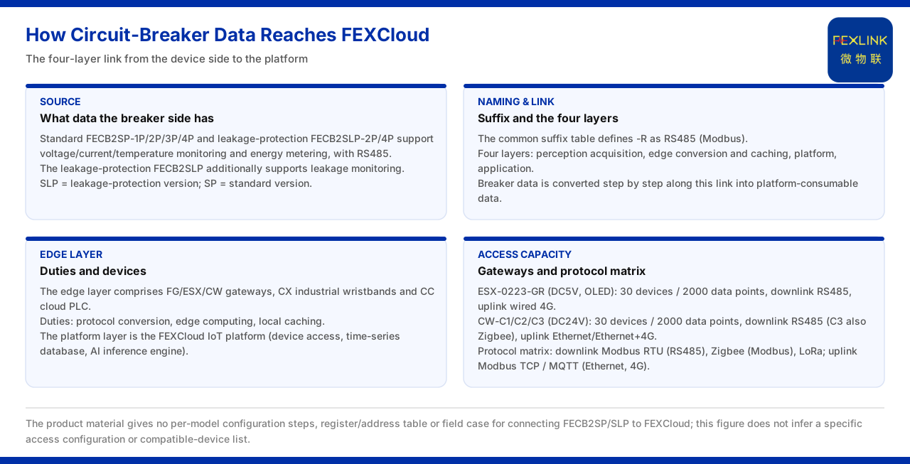
How Does Circuit-Breaker Data Connect to FEXCloud?
If an intelligent circuit breaker leaves voltage, current and temperature values only locally, its value to a distribution system is reduced to protection actions. To bring these data into the platform and let them participate in trend analysis and alarms, a link from device to cloud must be established. The product knowledge base splits this link into four layers: perception-layer acquisition, edge-layer conversion and caching, platform-layer reception, and application-layer use. Connecting circuit-breaker data to FEXCloud is essentially converting the Modbus messages on the device side step by step into platform-consumable data along this link.
This article follows the knowledge base records to explain what data the circuit-breaker side provides, what the edge layer is responsible for, how the communication protocols connect, and what the platform layer FEXCloud does. It should first be noted that the material gives a viable architectural path, not the configuration steps of any specific model.
1. What Data the Circuit-Breaker Side Must First Have
The intelligent circuit-breaker model table of the knowledge base lists two kinds of product. The intelligent circuit breaker (standard model) covers FECB2SP-1P and FECB2SP-2P and FECB2SP-3P and FECB2SP-4P; the intelligent circuit breaker (with residual-current protection) covers FECB2SLP-2P and FECB2SLP-4P.
Both kinds support voltage, current and temperature monitoring as well as electricity consumption, and both communicate over RS485; the residual-current model additionally supports leakage-current monitoring. That is, the circuit-breaker side provides not only switch state but also measurement results of electrical quantities. Voltage, current, temperature and electricity consumption form the basic data of demand-side monitoring, while leakage-current monitoring is the criterion source on the residual-current side. Whether the data can go to the cloud depends on whether these values can be read out and converted one by one, not on whether the breaker itself is networked.
2. The Difference Between the Standard and Residual-Current Models
The knowledge base notes the meaning of the model suffixes: SLP is the residual-current model, combining leakage-current monitoring and residual-current protection; SP is the standard model. This distinction determines the coverage of the same series on the data plane.
The naming difference corresponds directly to a difference in monitoring capability. The standard model covers voltage, current, temperature and electricity consumption; the residual-current model adds leakage-current monitoring on top. For a designer, this means selection must first judge whether the circuit needs residual-current monitoring, and then fix the pole count and model. For data access, both kinds output over RS485, so the first half of the cloud path is common and the difference lies only in whether a leakage-current data object exists on the circuit-breaker side.
3. Naming Basis of the Suffix and Communication Method
The general suffix table of the knowledge base defines -R as RS485 (Modbus). This provides the naming basis for judging the communication method of this series of breakers: when a model carries -R, its communication uses RS485 and corresponds to the Modbus protocol.
Reading the suffix together with the model table allows one to judge the communication interface from the name first and then check the monitoring items against the model table. The meaning of this reading is that the knowledge base encodes the communication method into the model, so that the device can be fixed as belonging to the RS485 side already at the selection stage. This article explains the communication method on this basis and does not additionally infer baud rate, register address or slave number that the material does not list.
4. What the Edge Layer Is Responsible For
The knowledge base divides the monitoring system into four layers, in which the edge layer is composed of devices such as the FG-series gateway, the intelligent edge-computing gateway and industrial gateways, together with industrial wearables and cloud PLCs, and is responsible for protocol conversion, edge computing and local caching; the edge layer connects downward to the perception layer and upward to the platform layer FEXCloud.
These three duties explain why circuit-breaker data must pass through the edge layer. Protocol conversion turns the device-side interface and protocol into a form the platform can receive; edge computing lets part of the processing be completed on site; local caching keeps data from being lost when the link is interrupted. For large numbers of dispersed breakers, the edge layer is the data convergence point and the conversion gateway between the field and the cloud. Without the edge layer, the values on RS485 cannot directly enter a platform carried over an IP network.
5. The Complete Link From Device to Platform
The communication-protocol matrix of the knowledge base gives the complete convention of the cloud path. The device downlink uses Modbus RTU (RS485), Zigbee (Modbus) and LoRa; the device uplink uses Modbus TCP or MQTT, carried over Ethernet and 4G, and at the gateway level optionally supports IEC 61850.
Placing downlink and uplink side by side makes the link clear: the breaker hands data to the edge layer over RS485 with Modbus RTU, and the edge layer uploads it to the platform over Ethernet with Modbus TCP or MQTT. The uplink and downlink protocols differ, and it is precisely this conversion that the edge layer must complete. IEC 61850, as an optional gateway-level uplink protocol, shows that in specific scenarios the edge layer can also provide another upward interface. The knowledge base gives no per-model register table or configuration steps, so this article describes only the protocol path and does not expand a concrete point table.
6. Access Capability of Edge-Layer Devices
The model table of the knowledge base gives the capability conventions of some edge-layer devices. The intelligent edge-computing gateway ESX-0223-GR has a DC5V supply with an OLED display, an access capacity of 30 devices and 2000 data points, RS485 downlink and wired 4G uplink.
The industrial gateways CW-C1, CW-C2 and CW-C3 have a DC24V supply and the same access capacity of 30 devices and 2000 data points; on the downlink, C1 and C2 use RS485 and C3 also includes Zigbee; on the uplink, they use Ethernet and Ethernet plus 4G respectively. Placing access capacity in the context of the cloud link shows that 30 devices and 2000 data points are the convergence scale of one edge-layer unit, determining how large a collection of distribution circuits one gateway can take on. The difference in uplink interface affects the choice of field networking method.
7. What the Platform Layer FEXCloud Takes On
The knowledge base defines the platform layer as the FEXCloud IoT cloud platform, responsible for device access, the time-series database and the AI inference engine. After circuit-breaker data is converted by the edge layer, device access is completed here, the data is written to the time-series database and made available to the AI inference engine.
This layer answers "what is done with the data once it reaches the cloud". Device access resolves connection and identity; the time-series database resolves storage and retrieval by time; and the AI inference engine performs further analysis on the data. The endpoint of connecting circuit-breaker data to FEXCloud is not displaying a reading but letting measurement results enter a data system that can be continuously analysed. The application layer, on top of this, carries concrete business use and differs from the platform layer in its division of labour.
Applicability and Limits
- This article restates only what the knowledge base lists; its factual boundary is the models and monitoring items of the intelligent circuit breaker, the suffix definition, the four-layer architecture of the monitoring system, the communication-protocol matrix, the access capability of edge-layer devices, and the duties of the platform layer FEXCloud.
- The pole counts, monitoring items and communication method of FECB2SP and FECB2SLP are cited as listed; this article does not infer rated current, breaking capacity or installation dimensions.
- The correspondence of -R with RS485 and Modbus is cited under the general suffix table; this article does not infer concrete baud rate, register address or slave parameters.
- The downlink interfaces, uplink methods and access capability of the edge-layer devices are cited as listed; this article does not infer their field networking details.
- The knowledge base gives no per-model configuration steps, registers or address table for connecting a circuit breaker to FEXCloud, nor a compatible-device list or field case; this article adds none of these and does not infer a concrete access configuration from the existing text.