 FEXLINK Research Institute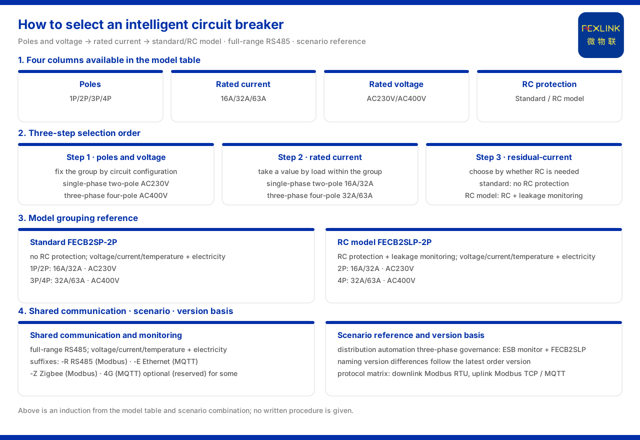
Direct answer
The product knowledge base does not give a written "intelligent circuit breaker selection procedure". The selection dimensions that can be confirmed come from several columns in the model table: poles, rated current, rated voltage and residual-current protection. Organizing these columns yields a three-step order — first fix the poles and rated voltage by circuit configuration, then set the rated current by load, and finally choose the standard or residual-current model according to whether residual-current protection is needed. Taking the FECB2SP intelligent circuit breaker (standard model) (e.g., FECB2SP-2P) and the FECB2SLP intelligent circuit breaker (with residual-current protection) (e.g., FECB2SLP-2P) as examples, 1P/2P is grouped with AC230V, 3P/4P with AC400V, the rated current is taken among the three tiers 16A, 32A and 63A, and residual-current protection is reflected as the distinction between the standard model and the residual-current model. It should be noted that the knowledge base does not give an overload-margin rule for load matching, so how to leave margin after step three is not inferred in this article and needs to be confirmed per the project scheme.
1. First, confirm: there is no written selection procedure
Before giving the steps, a premise must first be stated: the knowledge base does not give a written intelligent circuit breaker selection procedure. What it provides is a model table and scenario combinations, not a passage of "do this first, then that". The columns available in the model table include: poles (1P/2P/3P/4P), rated current (16A/32A/63A), rated voltage (AC230V/AC400V) and residual-current protection (standard model and residual-current model). The knowledge base also has the "distribution automation three-phase governance" scenario combination and a note that naming version differences are subject to the latest order version. Therefore, the three-step order below is the result of organizing these existing columns and scenarios; it is an induction, not a written procedure originally in the knowledge base.
2. Step one: fix poles and rated voltage by circuit configuration
The first step is to determine the poles and rated voltage. The model table gives the two as a group: for the FECB2SP intelligent circuit breaker (standard model), 1P/2P corresponds to 16A/32A and AC230V, while 3P/4P corresponds to 32A/63A and AC400V. The FECB2SLP intelligent circuit breaker (with residual-current protection) follows the same grouping: 2P corresponds to 16A/32A and AC230V, and 4P corresponds to 32A/63A and AC400V. It can be seen that poles and rated voltage are bound together: single-phase and two-pole form one group, three-phase and four-pole another. In selection, confirming first whether the circuit is single-phase or three-phase simultaneously fixes the two columns of poles and rated voltage. This step is placed first because it determines which current tiers and residual-current models can be chosen later.
3. Step two: set rated current by load
The second step is to choose the rated current within the group already fixed. In the standard model, the selectable currents for 1P/2P are 16A and 32A, and for 3P/4P they are 32A and 63A; in the residual-current model, 2P gives 16A and 32A, and 4P gives 32A and 63A. The current tiers of the two groups do not fully overlap: single-phase two-pole is 16A, 32A, and three-phase four-pole is 32A, 63A. After the first step's grouping is fixed, the second step is to take a value by load within the current tiers given by that group. It should be noted that the knowledge base does not give a rule for calculating the overload margin by load, so the judgment of "how large a load should select which tier" is outside the knowledge base's basis, and this article does not supplement this rule.
4. Step three: choose standard or residual-current model
The third step is to determine whether residual-current protection is needed. The model table distinguishes two prefixes: the standard model and the residual-current model. The standard model has no residual-current protection and supports voltage, current, temperature monitoring and electricity consumption; the residual-current model supports residual-current protection, leakage monitoring, voltage, current, temperature monitoring and electricity consumption. Both support voltage, current, temperature monitoring and electricity consumption, with the difference concentrated in the two items of residual-current protection and leakage monitoring. That is, the criterion of the third step is whether the circuit needs residual-current protection and leakage monitoring: if so, choose the residual-current model; if not, choose the standard model. The knowledge base encodes this difference directly in the prefix, so selection need not compare items in the parameter table one by one — the prefix is enough to distinguish them.
5. Shared communication and monitoring functions
The two models are common in communication and basic monitoring functions. The knowledge base records that the whole intelligent circuit breaker series uses RS485 communication and supports voltage, current, temperature monitoring and electricity consumption; the appendix model quick-reference positions both the standard model and the residual-current model as intelligent circuit breakers. Seen within the general suffix rules, -R is RS485 (Modbus), -E is Ethernet (MQTT) and -Z is Zigbee (Modbus), with 4G (MQTT) optionally available (reserved) for some products; in the communication protocol matrix, the device downlink includes Modbus RTU (RS485), the uplink includes Modbus TCP or MQTT (Ethernet, 4G), and the gateway level may optionally include IEC 61850. These are access conditions to confirm together in selection, but they do not change the preceding three-step order; rather, they supplement networking after the three steps.
6. Scenario reference and version statement
In the "distribution automation three-phase governance" scenario, the recommended combination given by the knowledge base is the ESB three-phase imbalance monitor plus the FECB2SLP intelligent circuit breaker (with residual-current protection). This combination gives two hints for selection: first, the three-phase governance scenario falls in the three-phase four-pole group, consistent with the grouping of the first two steps; second, the scenario directly selects the residual-current model, showing that in scenarios requiring leakage monitoring, the residual-current model is the landing point given by the knowledge base. In addition, the knowledge base states in its known information gaps that the naming of some sheets of the 2025 selection manual (such as the intelligent circuit breaker) and the model-rule document differ by version, and that the latest order version governs. Therefore, after the third step determines the model, the naming and configuration should also be checked against the latest order version.
7. Writing the three steps as a sequence
Reducing the above threads to one sequence: step one, fix the poles and rated voltage by circuit configuration, single-phase two-pole being AC230V and three-phase four-pole being AC400V; step two, set the rated current by load among the current tiers given by that group, single-phase two-pole being 16A/32A and three-phase four-pole being 32A/63A; step three, choose the standard or residual-current model according to whether residual-current protection is needed, selecting the residual-current model when residual-current protection and leakage monitoring are required; step four, confirm the communication access according to the general suffixes and protocol matrix. It should again be emphasized that the knowledge base does not give a written selection procedure, nor an overload-margin rule; the above order is the result of organizing the columns of the model table and the scenario combination, for checking item by item during selection, rather than a procedure specified by the knowledge base.
Scope and limitations
First, this article only restates content listed in the product knowledge base, and its factual boundary is limited to the poles, rated current, rated voltage and residual-current columns of the intelligent circuit breaker model table, the whole series' RS485 communication and monitoring functions, the appendix model quick-reference, the distribution automation three-phase governance scenario combination, and the general suffixes, communication protocol matrix and naming version-difference statement.
Second, the knowledge base does not give a written intelligent circuit breaker selection procedure; the three-step order in this article is induced from the columns of the model table, the scenario combination and the version basis, and does not mean that the knowledge base gives a statutory or specified selection procedure.
Third, the knowledge base does not give an overload-margin rule for load matching, and this article does not supplement or infer this rule.
Fourth, the 16A/32A and AC230V for 1P/2P and the 32A/63A and AC400V for 3P/4P of the FECB2SP intelligent circuit breaker (standard model), the 16A/32A and AC230V for 2P and the 32A/63A and AC400V for 4P of the FECB2SLP intelligent circuit breaker (with residual-current protection), and the whole series' RS485 and voltage/current/temperature monitoring and electricity consumption are all based on the knowledge base's stated basis, and this article does not infer the specific configuration of unlisted models from them.
Fifth, that naming version differences are subject to the latest order version is based on the knowledge base's stated basis, and this article does not infer the difference details of any historical version from it.
Sixth, this article does not constitute a commitment to the selection result or on-site performance of any specific project; actual conditions are subject to the latest product documentation and project scheme.