 FEXLINK Research Institute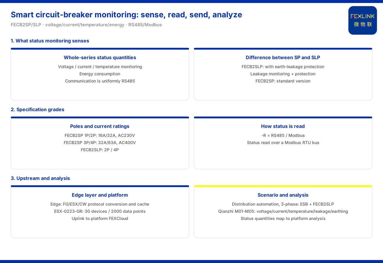
Direct answer
State monitoring of an intelligent circuit breaker answers the question "is the electrical state of the distribution circuit normal at this moment". The full FECB2SP intelligent circuit breaker (standard model; e.g. FECB2SP-1P) and FECB2SLP intelligent circuit breaker (with residual-current protection; e.g. FECB2SLP-2P) series listed in the product knowledge base all support voltage, current and temperature monitoring and support energy consumption, with communication uniformly RS485. The two differ in their trade-off of functions: FECB2SLP is the residual-current version, adding leakage monitoring and residual-current protection on top of voltage, current and temperature monitoring and energy consumption; FECB2SP is the standard version. State quantities are read through RS485 and Modbus, then ascend to the platform through the edge layer's protocol conversion and local buffering. The corresponding analytical capability on the platform side can cover state quantities such as voltage, current, temperature and leakage. State monitoring of an intelligent circuit breaker can therefore be summarised as four links: "what to acquire, how to read, where to send, and who analyses".
Objects of state monitoring: voltage, current, temperature and energy consumption
The intelligent circuit-breaker table in the product knowledge base states that the full FECB2SP and FECB2SLP series support voltage, current and temperature monitoring and support energy consumption, with RS485 communication. These four items form the basic objects of intelligent circuit-breaker state monitoring: voltage and current reflect the electrical characteristics of circuit operation, temperature reflects whether there is a tendency to overheat at connections and conductors, and energy consumption is used for cumulative metering. Listing them side by side shows that an intelligent circuit breaker not only performs make/break but also continuously acquires the circuit state. State monitoring thus extends the circuit breaker from a mere switching element into a distribution node with sensing capability, so that circuit operating information can be acquired at the same position.
The difference between the standard model and the residual-current model
On top of the basic state quantities, the product knowledge base notes that SLP denotes the residual-current version, with leakage monitoring and residual-current protection, and SP denotes the standard version. As to specific models, FECB2SLP-2P and FECB2SLP-4P add leakage monitoring on top of voltage, current and temperature monitoring and energy consumption. This means leakage monitoring is not standard across the whole series but is a state quantity only the residual-current version provides. In selection, first judge whether the protected circuit needs leakage monitoring: choose the residual-current version if it does and the standard version if it does not, the two being identical in the basic state quantities. Because leakage monitoring comes with residual-current protection, choosing the residual-current version also brings residual-current protection into that circuit.
How pole count and current specifications are tiered
The product knowledge base gives the tiers by pole count. FECB2SP in 1P and 2P has rated currents of 16A and 32A at rated voltage AC230V; in 3P and 4P it has rated currents of 32A and 63A at rated voltage AC400V. FECB2SLP offers 2P (16A and 32A, AC230V) and 4P (32A and 63A, AC400V). This shows that the state-monitoring capability covers different pole counts and current specifications: single-phase circuits fall in the 1P and 2P tier, three-phase circuits in the 3P and 4P tier. In selection, first determine the pole count by the circuit phases, then pick within the corresponding rated current.
How state quantities are read out: RS485 and Modbus
The acquired state quantities need a uniform way of being read. The general suffix rule in the product knowledge base specifies that -R denotes RS485 and Modbus, and the whole intelligent circuit-breaker series communicates over RS485, so state quantities such as voltage, current, temperature and energy consumption can be read over the Modbus RTU bus. Unifying communication on RS485 has the benefit of consistent reading: whether standard version or residual-current version, state quantities are acquired in the same bus manner, and the edge side does not need different access methods for different models.
How the edge layer consolidates these state quantities
Once read out, the state quantities still need consolidation and upload. In the general four-layer architecture of the product knowledge base, the intelligent circuit breaker sits on the distribution and execution side, and its data ascends to the platform layer through the edge layer's protocol conversion, edge computing and local buffering. Among the edge devices given by the product knowledge base, the intelligent edge-computing gateway ESX-0223-GR and the industrial gateway CW-C1, CW-C2 and CW-C3 all provide RS485 downlink and can connect 30 devices and 2000 data points. These parameters show that the state quantities of intelligent circuit breakers have explicit receiving devices and capacity figures at the edge layer; consolidation is not estimated by experience but has a checkable access scale. Under this convention, multiple intelligent circuit breakers can be consolidated into the same gateway and then uploaded uniformly, avoiding each device networking independently.
Corresponding analysis on the platform side
After the data ascends to the platform, corresponding analytical capability is needed. The basic vital-signs sub-models in the product knowledge base cover voltage, current, temperature, leakage and grounding, where leakage analysis includes temporal trends and grounding analysis includes grounding-system type identification. This coverage corresponds exactly to the state quantities the intelligent circuit breaker acquires: the voltage, current, temperature and leakage it collects all find corresponding analytical sub-models on the platform side. The product knowledge base also gives a combination example in its typical scenarios: distribution-automation three-phase governance recommends the ESB three-phase imbalance monitor together with the FECB2SLP intelligent circuit breaker, showing that state monitoring can coordinate with power-quality monitoring. The point of this coordination is that one distribution cabinet can show both whether the three phases are balanced and the voltage, current and temperature of each circuit.
Checking sequence
Gathering the clues above into a sequence, four steps can be followed. First, determine the pole count by the circuit phases—whether it falls in 1P and 2P or 3P and 4P. Second, choose the specification within the corresponding rated current and rated voltage. Third, judge whether leakage monitoring is needed and trade off accordingly between the standard version and the residual-current version. Fourth, confirm whether the edge-layer access devices and capacity are sufficient and let the corresponding platform-side sub-models take over the analysis. In this order, the answer is how the four links "what to acquire, how to read, where to send and who analyses" align.
Applicability and limits
First, this article only restates content listed in the product knowledge base; its factual boundary is limited to the state-monitoring objects of the FECB2SP and FECB2SLP intelligent circuit breakers, the difference between the standard version and the residual-current version, the pole-count and rated-current tiers, the communication method, the general four-layer architecture and edge-layer access capacity, the coverage of the platform-side basic vital-signs sub-models, and the combination in typical scenarios, and it introduces no unlisted parameters, certifications or cases.
Second, the state-monitoring objects and communication method of the whole intelligent circuit-breaker series, the difference between the standard version and the residual-current version, and the pole-count, rated-current and rated-voltage tiers are all cited on the terms listed in the product knowledge base.
Third, the correspondence between the general suffixes and Modbus is cited on the terms listed in the product knowledge base; this article draws no conclusion on the sampling period or reporting frequency of a specific project.
Fourth, the edge-layer access devices and their device and data-point capacity, and the coverage of the platform-side basic vital-signs sub-models, are all cited on the terms listed in the product knowledge base.
Fifth, this article only explains how the intelligent circuit breaker acquires, reads and consolidates state monitoring and provides no selection, setting or configuration calculation for a specific project.
Sixth, this article does not commit to any specific project's selection result or on-site performance, which remain subject to the latest product documentation and project scheme.