 FEXLINK Research Institute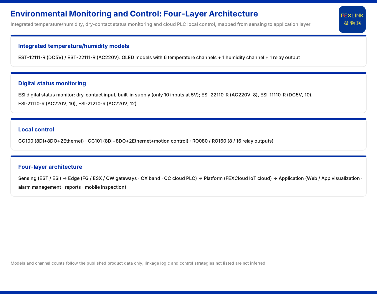
Direct answer
If environmental monitoring only collects and does not interlock, data stops on the screen; only when collection and control are placed in the same chain can a temperature or humidity over-limit trigger an action locally. Based on the wording listed in the product documentation, this article explains how the multi-channel temperature intelligent controller provides temperature, humidity, and one relay output on a single device, how the digital-input status monitor collects dry-contact signals, how the cloud PLC and relay expansion carry local control, and where these capabilities sit in the four-layer architecture; it infers no control strategy for any specific site.
1. Why environmental monitoring needs one control channel
Temperature and humidity are the two most basic quantities of environmental hazards. High temperature may mean poor heat dissipation or load overload; high humidity may cause condensation and reduced insulation. If the value is only read and no action is taken, an anomaly can only wait to be discovered. With one or more control outputs, the system can interlock locally when a limit is exceeded.
This connects monitoring with control. Monitoring is responsible for discovery and control for response, and only on the same chain can the time from discovery to handling be shortened. The product documentation sets separate segments for humidity and relay output in the model rules, which shows precisely that this need for collection plus control has been brought into the product design. The product documentation gives the capability wording, and this article does not infer the specific interlocking logic and thresholds.
2. Combined temperature and humidity models
The product documentation states that the multi-channel temperature intelligent controller (EST-12111-R) is powered by DC5V and the multi-channel temperature intelligent controller (EST-22111-R) is powered by AC220V, and both are OLED models with 6 channels of temperature plus 1 channel of humidity plus 1 relay output. In the model rules, the humidity segment is 1 channel of humidity.
Putting these three capabilities on one device matters for integration. The 6 channels of temperature cover several measurement points in one cabinet, the 1 channel of humidity adds the ambient humidity dimension, and the 1 relay output provides a local control outlet. The power supply comes in DC5V and AC220V, showing that the device can adapt to different supply conditions. The product documentation also states that the 6-channel and 8-channel models of the EST support 1 relay output, which can be used for local control in environmental interlocking. The product documentation gives the model configuration, and this article does not infer relay contact capacity or load capability.
3. Digital status monitoring: dry-contact input
Beyond analogue quantities, environmental interlocking also needs to read the switch status of devices. The product documentation states that the digital-input status monitor (ESI series) uses dry-contact input with a built-in power supply, and at 5V supply it can only provide 10 input channels. Its models include: the digital-input status monitor (ESI-22110-R) with AC220V and 8 channels; the digital-input status monitor (ESI-11110-R) with DC5V and 10 channels; the digital-input status monitor (ESI-21110-R) with AC220V and 10 channels; and the digital-input status monitor (ESI-21210-R) with AC220V and 12 channels.
Dry-contact input suits reading passive contact signals such as access control and fan operation feedback. The built-in power supply shows that it does not rely on external power for the contacts. The statement that at 5V supply it can only provide 10 input channels is a constraint to note: the supply method affects the available channel count. Arranging the models by channel count shows three tiers of 8 channels, 10 channels, and 12 channels. The product documentation gives the models and channel counts, and this article does not expand the timing and debounce processing of input signals.
4. Local control: cloud PLC and relay expansion
Beyond collection, control needs an actuator. The product documentation states that the cloud PLC main unit (CC100) has 8 digital inputs plus 8 digital outputs plus 2 Ethernet ports; the cloud PLC main unit (CC101) adds motion control on this basis. The digital-output expansion provides relay output in 8-point and 16-point versions, with the corresponding models being the output expansion (RO080) and the output expansion (RO160).
The cloud PLC provides programmable control logic and digital input/output, and the main unit carries Ethernet for easy networking; the expansion modules add relay output points as needed, so that a small system can expand as points grow. In this way, the closed loop of reading status and executing action lands on the edge side. The product documentation gives the configuration of the main unit and expansions, and this article does not infer the programming method or response time.
5. The four-layer architecture and channels
The product documentation states that the general four-layer monitoring-system architecture is the perception layer, the edge layer, the platform layer, and the application layer. The perception layer includes the various monitoring modules, smart meters, and sensors; the edge layer is carried by the FG, ESX, and CW gateways, the CX industrial wearable, and the CC cloud PLC, which handle protocol conversion, edge computing, and local caching.
Placing this topic's capabilities into the four layers: temperature and humidity collection and dry-contact collection belong to the perception layer; local control logic is executed by the cloud PLC at the edge layer; and data goes up to the platform layer through the gateway. The product documentation gives the duties of the four layers and the edge-layer composition, and this article does not infer the specific topology of any site.
6. Platform layer and application layer
The product documentation states that the platform layer is the FEXCloud IoT cloud platform, which handles device access, time-series database, and AI inference engine; the application layer includes Web and App visualisation, alarm management, analysis reports, and mobile inspection. The platform layer handles data inflow and intelligent processing, and the application layer presents results to users.
For environmental monitoring, after temperature, humidity, and status quantities enter the platform, they can be used for trend viewing and alarm management; mobile inspection extends the viewing capability to the field. The platform layer and the application layer do not directly execute control, yet they determine whether monitoring data can be used effectively. The product documentation gives the functional composition of each layer, and this article does not infer the specific report fields and alarm rules.
7. Three questions for selection and placement
Bringing the whole article together, selection can begin by answering three questions. First, which quantities need to be collected? If temperature plus humidity is needed, choose a model with the humidity segment; if only switch status needs reading, the digital-input status monitor can be chosen. Second, is local control needed? If an over-limit should act at once, choose a model with relay output, or configure the cloud PLC and relay expansion. Third, what is the supply condition? The DC5V and AC220V model types must match the field supply, and note the limit of 5V supply on the input channel count.
After answering these three points, place the devices into the four-layer architecture, and a complete chain of sensing collection, edge execution, platform aggregation, and application presentation is formed. The product documentation does not give the quotation or delivery information of each model, and this article does not infer it.
Scope and limitations
First, this article restates only the wording listed in the product documentation; its factual boundary is the multi-channel temperature intelligent controller (EST-12111-R, DC5V) and (EST-22111-R, AC220V) with 6 channels of temperature plus 1 channel of humidity plus 1 relay output, the model rules containing 1 channel of humidity, and the 6-channel and 8-channel EST models supporting 1 relay output; the digital-input status monitor (ESI series) with dry-contact input and a built-in power supply, at 5V supply providing only 10 input channels, with models ESI-22110-R (AC220V, 8 channels), ESI-11110-R (DC5V, 10 channels), ESI-21110-R (AC220V, 10 channels), and ESI-21210-R (AC220V, 12 channels); the cloud PLC main units CC100 (8 digital inputs plus 8 digital outputs plus 2 Ethernet ports) and CC101 (adding motion control), and the digital-output expansion RO080 (8-point relay output) and RO160 (16-point relay output); the four-layer architecture of the perception layer, edge layer, platform layer, and application layer, with the edge layer carried by the FG, ESX, and CW gateways, the CX industrial wearable, and the CC cloud PLC handling protocol conversion, edge computing, and local caching; and the platform layer FEXCloud handling device access, time-series database, and AI inference engine, with the application layer including Web and App visualisation, alarm management, analysis reports, and mobile inspection.
Second, this article does not infer relay contact capacity, control response time, or programming method, nor the interlocking strategy and thresholds of any specific site.
Third, the model configuration, input channel counts, and four-layer architecture are product-documentation wording, and field supply, point placement, and interlocking logic belong to engineering-design judgement.
Fourth, specific selection and configuration should follow the latest product documentation, the relevant standards, and the project scheme.