 微物联研究院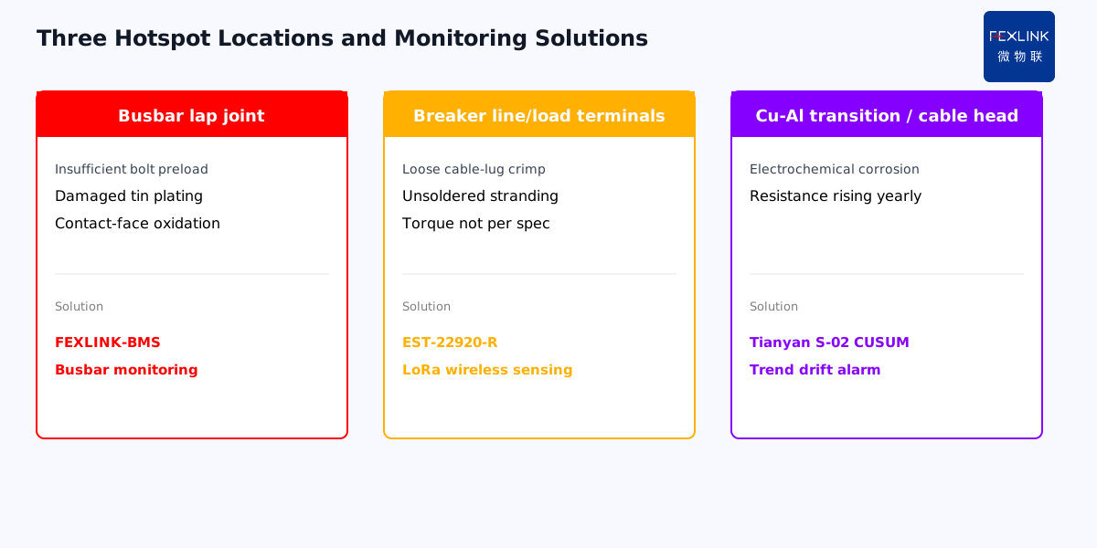
Direct Answer
There is no single limit. GB/T 7251.1 (Low-voltage switchgear and controlgear assemblies — Part 1: General rules) prescribes different temperature-rise limits for different parts inside the enclosure: busbar joints, wire terminal blocks, breaker internal contacts, insulation surfaces, and touchable exterior panels each have their own ceiling. Walking the floor and applying "nothing above 70 °C" to every point either flags healthy contacts or misses a genuinely overheating busbar.
At a 10 kV substation in an industrial park, the contractor signed off on "acceptance passed" after an infrared scan showed a maximum of 68 °C. Six months later, a phase-A main busbar joint burned through and shut down the load. Post-mortem: the point had been running above 95 °C against a 32 °C ambient — a 63 K rise, already exceeding the 60 K limit GB/T 7251.1 sets for bare-copper busbar joints. The acceptance check looked at absolute temperature, never computed rise above ambient, and never distinguished one location from another.
1. How GB/T 7251.1 actually defines temperature rise
The standard measures temperature rise, not absolute temperature. Rise = measured point temperature − surrounding air temperature. The reason is practical: a cabinet on a 40 °C summer day and a 5 °C winter day show 35 °C different absolute readings for the same heat generation. Rise lets you compare across seasons and sites.
Table 7 of GB/T 7251.1 splits interior locations into categories, each with its own rise limit in K:
| Location category | Typical point | Rise limit (K) |
|---|---|---|
| Bare-copper busbar joint | Lap bolts, tinned contact faces | 60 |
| Insulated-wire terminal | Breaker lugs, cable terminals | 70 |
| Interior metal surfaces | Mounting plates, brackets (not touchable) | 80 |
| Touchable exterior | Cabinet doors, side panels (hand-accessible) | 25 (metal) / 35 (insulating) |
| Insulating supports | Busbar clamps, barriers | Per material grade |
The 60 K busbar-joint limit is the tightest band. Busbars carry high current; once a lap joint oxidizes, contact resistance feeds on itself: heat → oxidation → higher resistance → more heat. The 60 K ceiling is the safety margin around that positive feedback.
2. Where the "70 °C" myth comes from
The vague "under 70 °C inside the cabinet" rule of thumb usually comes from two misreadings stacked together:
First, people misremember the 70 K terminal rise limit as "70 °C absolute." A terminal is allowed to reach 110 °C at 40 °C ambient, but only 95 °C at 25 °C ambient. Locking the number at 70 °C assumes the ambient is fixed forever.
Second, people conflate the 25 K touchable-exterior limit (roughly 65 °C on a summer day — hot to the touch but not burn-grade) with interior allowables. Air inside a cabinet already runs 10–15 K above ambient; comparing busbar temperature to interior air temperature uses the wrong reference frame.
The correct procedure is two steps: measure ambient air (outside the cabinet, in ventilated space — not inside), measure the target point, subtract to get rise, then look up the limit for that specific location.
3. Where overheating actually concentrates
In field practice, temperature excess is not uniformly distributed; it clusters in three locations:
Busbar lap joints. Insufficient bolt preload, damaged tin plating, or oxide film on the contact face are the three leading causes of busbar rise failures. At an airport terminal 0.4 kV cabinet, the main busbar rise was 35 K at commissioning in 2019 and 58 K at re-test in 2024 — still under 60 in absolute terms, but climbing fast. A FEXLINK-BMS busbar monitoring system alarms at this stage, long before the 60 K hard limit.
Breaker line and load terminals. The 70 K terminal limit looks looser than the busbar, but breaker internal contacts are warranted by the manufacturer, while line/load terminals are field-wired — crimp quality varies wildly. Loose cable-lug crimps, unsoldered stranded conductors, or lugs not torqued to spec are common root causes. The EST multi-channel temperature controller (EST-22920-R LoRa wireless node) sticks directly onto the terminal at a 10-second sampling interval. Overlaying the temperature curve on the load-current curve makes "current normal, temperature creeping" — the signature of a loose contact — obvious.
Cable head to busbar transitions. Copper-aluminum transition plates with poor contact-surface preparation suffer electrochemical corrosion that raises contact resistance year over year. This type of overheating is a slow drift: a few K per year, but over ten years it can climb from 30 K to 80 K. The Tianyan engine S-02 CUSUM test runs a cumulative-sum check on the temperature series; it is far more sensitive to slow drift than a fixed threshold. A fixed threshold waits until 60 K to alarm; CUSUM may flag the trend at 45 K.
4. Correct acceptance and inspection practice
At acceptance, run the GB/T 7251.1 temperature-rise test: energize at rated current until thermal equilibrium (typically 8+ hours), measure rise at each category of point with thermocouples or infrared, and record against the limit table line by line. This is the manufacturer and installer's responsibility. The user should receive a stamped test report, not just a single infrared image captioned "nothing looks hot."
In operation, infrared inspection at least annually, but the point is not "scan everything." It is:
- Fix measurement at key locations (main busbar laps, incoming terminals, bus-tie, heavy-load feeders)
- Record ambient temperature and load current at the time of reading
- Compare against prior readings under similar conditions
- Flag points with annual rise increment above 5 K for watch-list status
At a data-center substation equipped in 2023 with an EST multi-channel temperature controller, two years of continuous data showed the B-section busbar clamp slowly drifting from 38 K to 52 K, with ambient and load unchanged. The system raised a YJ2 early-warning at 48 K; scheduled power-down inspection found the clamp bolt loose by half a turn. Waiting until 60 K would almost certainly have resulted in erosion.
5. Where to place monitoring sensors
Not every point in a cabinet needs a temperature sensor. Select by risk and location:
- Mandatory: main busbar line/load laps, bus-tie contacts, capacitor-switching contacts
- Recommended: heavy-load feeder terminals (>400 A), VFD inputs, PV interconnection points
- Optional: ordinary feeder terminals, lighting circuits, standby cabinets
The FEXLINK-BMS busbar monitoring system is a distributed busbar-specific solution: sensors adhere to lap faces and transmit LoRa wirelessly to an in-cabinet collector, no cable holes required. The EST multi-channel temperature controller is more flexible — 8- and 16-channel versions fit different cabinet sizes and are suited for terminal and cable-head retrofit points.
Scope and Limitations
This article references the current edition of GB/T 7251.1 temperature-rise limits; specific values follow the latest standard and manufacturer technical conditions. The industrial park, airport, and data-center cases are anonymized. Rise tests require rated-current thermal equilibrium; infrared readings are affected by surface emissivity and must be corrected by material. Sensor placement and count are determined by on-site electrical design.