 FEXLINK Research Institute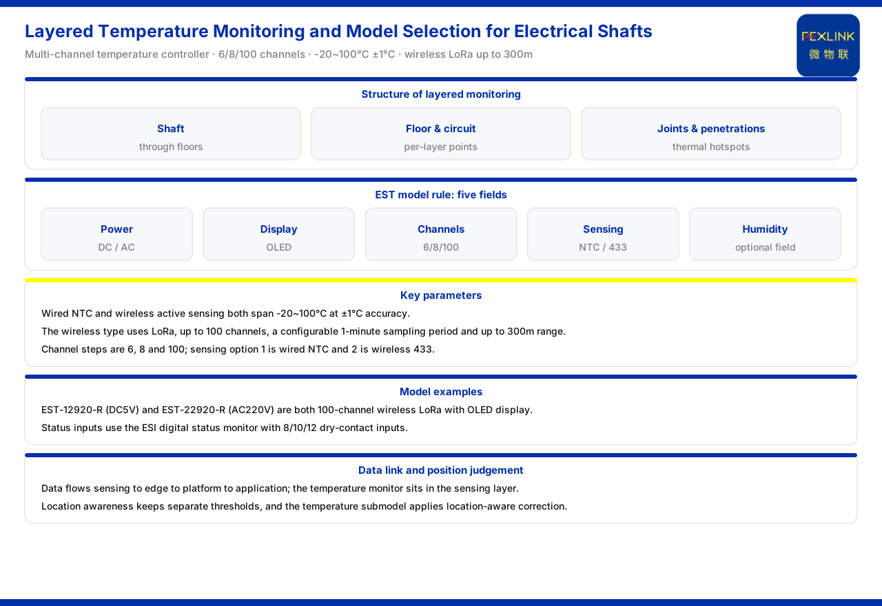
Direct answer
Layered temperature measurement in an electrical shaft comes down to two steps: placing measurement points by floor and judging risk by position. The product knowledge base records that the model rule of the multi-channel temperature intelligent controller (example model EST-12920-R) arranges power supply, display, channel count, measurement method and humidity in order; the measurement method divides into wired NTC and wireless, and the channel count divides by tier into 6 channels, 8 channels and 100 channels; both wired and wireless measurement cover -20℃ to 100℃ with ±1℃ accuracy. The wireless variant uses LoRa communication, with a maximum of 100 channels, a sampling period settable to 1 minute and an effective distance of not more than 300 metres, which suits layered networking from top to bottom in a shaft. Status quantities can be connected through the digital-input status monitor, which provides 8, 10 or 12 dry-contact inputs. Data is uploaded level by level through the perception layer, the edge layer, the platform layer and the application layer; position awareness maintains independent thresholds for different types of electrical position, and the temperature sub-model applies a position-aware correction. This article only restates the specifications above.
Why shaft temperature should be layered
An electrical shaft runs through several floors, and cable joints, floor-penetration points and distribution nodes on each floor sit at different heights. Temperature anomalies tend to concentrate at joints and connections, and these positions are distributed with height, so measuring at a single height cannot represent the state of the whole shaft. The point of layered measurement is to give each floor or each circuit a measurement point suited to its position, so that "which floor is heating up" and "how large the rise is" can be observed separately. If the points are concentrated in one place, the floor where the anomaly originates cannot be judged; once placed by floor, the data can be mapped to a position and provide a basis for later risk judgement. Layering is not simply adding more points but making the point structure correspond to the physical structure of the shaft.
The measuring device: the multi-channel temperature controller
The main device carrying layered shaft temperature measurement is the multi-channel temperature controller. The knowledge base records that its model rule arranges "power supply, display, channel count, measurement method, humidity" in order, where in the measurement method 1 stands for wired NTC and 2 for wireless 433; the channel count is given by the three codes 1, 2 and 9, corresponding to 6 channels, 8 channels and 100 channels. By combining channel count and measurement method, one device can cover several circuits on a floor or a larger number of points along the whole shaft. Selection should first confirm how many points must be connected on each floor and then choose the channel tier accordingly, avoiding too few channels that later restrict expansion or too many that leave the deployment redundant. The power-supply and display fields in the model correspond to the on-site supply method and the need for local viewing.
Choosing between wired and wireless
The difference between wired and wireless directly affects the construction and networking of the shaft. The knowledge base records that wired NTC and wireless active measurement both cover -20℃ to 100℃ with ±1℃ accuracy; the wireless variant uses LoRa communication, with a maximum of 100 channels, a sampling period settable to 1 minute and an effective distance of not more than 300 metres. The wired method suits sites with concentrated points and convenient cabling; it is stable but needs wiring. The wireless method suits a shaft with scattered points across floors, reducing inter-floor cabling, but attention must be paid to the effective distance and signal conditions. The choice should be judged together with shaft height, inter-floor structure and installation conditions: if one segment has dense points close to the host, wired may be considered; if points are distributed over a long distance along the shaft, wireless layered networking is more flexible. The measurement range and accuracy of the two methods are the same in the knowledge base, and the difference lies mainly in communication and construction.
Model table and key parameters
The knowledge base model table lists that the wireless models EST-12920-R (DC5V supply) and EST-22920-R (AC220V supply) are both 100-channel wireless LoRa with an OLED display. This combination of fields shows that models of the same channel count and communication specification can be chosen as a DC or AC version according to the on-site supply condition. Matching these parameters with the model rule above shows that selection must confirm not only the channel count but also fields such as power supply, display and measurement method. It should be noted that the specific models in the table are examples listed in the knowledge base; this article does not infer the parameters of unlisted models, and actual choice should follow the latest product materials.
Status-quantity input: the digital-input status monitor
Besides temperature, a shaft also has status quantities such as access control and alarm contacts that need to be connected. The knowledge base records that the digital-input status monitor provides 8, 10 or 12 dry-contact inputs with a built-in power supply, and that with 5V supply it can serve only as 10 inputs. This means the choice of channel count for status input relates to the power-supply method: if 5V supply is used, the usable channels are limited. When temperature monitoring and status-quantity monitoring are considered in the same shaft plan, the channel count and supply of the two device classes should be confirmed separately, avoiding rework from insufficient points or a mismatched supply method. Uploading status-quantity data together with temperature data helps form a complete view of the shaft state on one platform.
How data is uploaded layer by layer: the four-layer architecture
For data collected in layers to be located and displayed, it must pass through a unified architecture. The knowledge base records that the general four-layer architecture of the monitoring system is: the perception layer (monitoring modules, smart meters, sensors and the like), the edge layer (gateways, acquisition and communication equipment), the platform layer (the cloud platform) and the application layer. The temperature monitor belongs to the perception layer; its data is uploaded through the edge layer to the platform and then displayed with layered positioning by the application layer. Understanding this structure helps plan "device deployment" and "data flow" separately: the perception layer solves collection, the edge layer solves stable transmission, the platform layer solves storage, and the application layer solves clear viewing. For layered shaft temperature measurement to produce a usable display, all four layers must be configured accordingly.
Distinguishing risk by position
The temperature data collected must ultimately land on risk judgement. The knowledge base records that position awareness maintains independent thresholds for 5 types of electrical topology position, and the temperature sub-model applies a position-aware correction. This shows that the same temperature reading may correspond to different risk conclusions at different positions, and layered temperature data can distinguish risk by position, thereby supporting the location of the floor where an abnormal shaft temperature rise originates. Putting the previous steps together: placing points by floor provides the data source; the model and communication provide the collection method; the four-layer architecture provides the data upload; and position awareness provides the risk landing point. The checked result should be confirmed together with on-site conditions; this article does not replace on-site verification.
Applicability and limits
First, the content of this article is limited to what the knowledge base lists: the model rule and key parameters of the multi-channel temperature controller, the input specification of the digital-input status monitor, the four-layer architecture of the monitoring system, and the existing entries on position awareness and the temperature sub-model correction.
Second, the -20℃ to 100℃ and ±1℃ of wired NTC and wireless measurement, the maximum of 100 channels of the wireless variant, the sampling period settable to 1 minute and the effective distance of not more than 300 metres are restated according to the knowledge base.
Third, EST-12920-R is an example listed in the knowledge base model table and EST-22920-R is likewise a listed example; this article does not infer the parameters of unlisted models, and actual choice should follow the latest product materials.
Fourth, the 8, 10 or 12 dry-contact inputs of the digital-input status monitor and the limitation that it can serve only as 10 inputs with 5V supply follow the knowledge base specification.
Fifth, shaft point placement, communication method and supply choice must be confirmed item by item together with on-site height and inter-floor structure; this article provides no specific engineering conclusion.